Light Source System and Display Apparatus Comprising the Light Source System

Inactive Publication Date: 2008-12-18
DELTA ELECTRONICS INC
View PDF14 Cites 5 Cited by
  • Summary
  • Abstract
  • Description
  • Claims
  • Application Information

AI Technical Summary

Benefits of technology

[0013]One objective of this invention is to provide a light source system and a display apparatus comprising the same. This light source system may deliver improved luminance, increased light emission efficiency and sufficient light flux, while maintaining a continuous light output as perceived by the human eye.

Problems solved by technology

However, as a kind of divergent light source, LED is restricted by the etendue conservation law that makes the light source effective only within a limited light source area and a limited angle.
Consequently, the luminance of the projection display apparatus cannot be improved by simply adding more LED light sources.
If a light beam from either of the LEDs impinges entirely or partially on such border regions, not only will light be lost, but also the instantaneous output light flux will be degraded.
As a result, the light beam projected on by an LED will actually occupy a substantial area on the mirror wheel 12, which makes it impractical to switch the LEDs on and off in advance to achieve a desired effect.
This will not only undoubtedly shorten the desirable “flat peak sections” and lengthen the unwanted “narrow trough sections” in the otherwise continuous light flux, but also exacerbate the discontinuity in the light flux and degrade the usage efficiency of the mirror wheel 12 significantly.
Each additional mirror wheel may further increase the size of the projection display apparatus significantly.
Therefore, in consideration of practical requirements on size of a projection display apparatus, luminance improvement this structure may provide is limited.
In summary, the LED light source structure used in the prior art projection display apparatuses has deficiencies, such as low light emission efficiency, limited room for the improvement of luminance and discontinuous light flux.

Method used


Image

  • Light Source System and Display Apparatus Comprising the Light Source System
  • Light Source System and Display Apparatus Comprising the Light Source System
  • Light Source System and Display Apparatus Comprising the Light Source System

Examples


Embodiment Construction

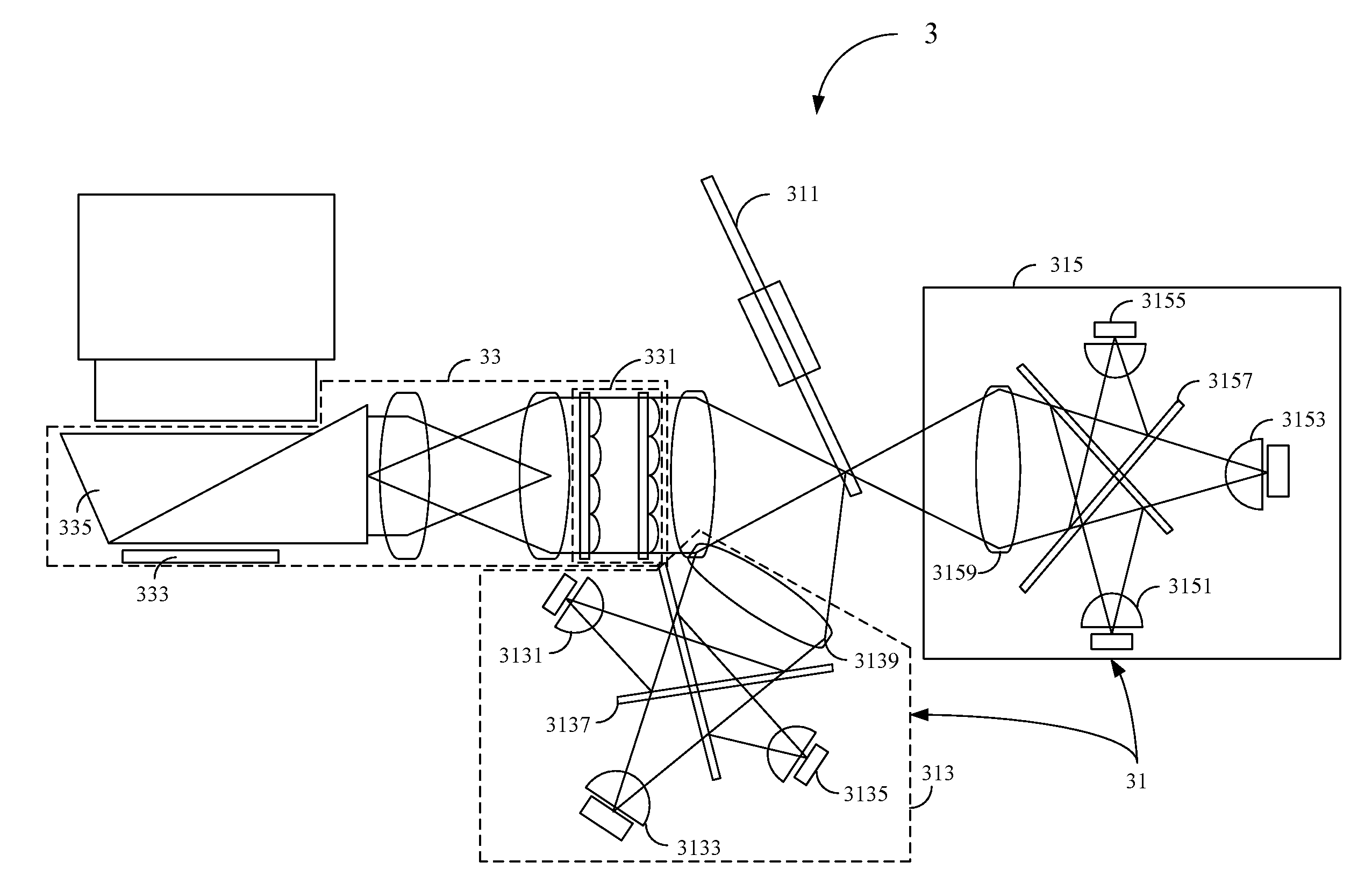
[0026]A display apparatus 3 in accordance with a first embodiment of this invention is depicted in FIG. 3A. The display apparatus 3, which in this embodiment is a projector, comprises a light source system 31 and an imaging system 33. The light source system 31, which is configured to provide a light beam for imaging, comprises a mirror wheel 311, a first light source module 313, a second light source module 315 and a controller (not shown).

[0027]As shown in FIG. 5A, the mirror wheel 311 has a central rotating shaft 310 and a body 312 which in this embodiment is shaped like a disc, for example, a disc of 5 cm in diameter (the diameter can be adjusted depending on the actual requirements). The body 312 is disposed at an outer edge of the central rotating shaft 310, and comprises an inner area and an outer area formed at an outer edge of the inner area. The outer area has a plurality of reflective segments 314 and a plurality of transmitting segments 316, with the reflective segments ...


PUM


Abstract

A light source system and a display apparatus comprising the light source system are provided. The display apparatus comprises the light source system and an imaging system. The light source system is configured to provide a light for imaging. The light source system comprises a mirror wheel and at least two light source modules, configured to provide at least two light beams respectively. These light beams are lit up according to a predetermined sequence. After being reflected by or directly passing through the mirror wheel, the light beams form a continuous light, traveling into the imaging system for imaging on a screen.

Description

[0001]This application claims priority to Taiwan Patent Application No. 096121738 filed on Jun. 15, 2007, the disclosures of which are incorporated herein by reference in their entirety.BACKGROUND OF THE INVENTION[0002]1. Field of the Invention[0003]The present invention provides a light source system and a display apparatus comprising the same, and particularly, relates to a light emitting diode (LED) light source system with high luminance and a display apparatus comprising the same.[0004]2. Descriptions of the Related Art[0005]Currently, more projection display apparatuses are adopting light emitting diodes (LEDs) as the light source in an attempt to increase the color gamut and decrease the power consumption. Because its short startup time and long life, light source of LED is used to replace high-pressure-mercury lamps in conventional projection display apparatuses. However, as a kind of divergent light source, LED is restricted by the etendue conservation law that makes the li...

Claims


Application Information

Patent Timeline
IPC IPC(8): F21V7/00
CPCG02B26/04H04N9/315H04N9/3164H04N9/3197
Inventor HUANG, JUNEJEI
Owner DELTA ELECTRONICS INC
Why Eureka
Try Eureka