Plasma Display Panel and Method of Manufacturing the Same

Inactive Publication Date: 2011-06-02
SAMSUNG SDI CO LTD
View PDF1 Cites 0 Cited by
  • Summary
  • Abstract
  • Description
  • Claims
  • Application Information

AI Technical Summary

Benefits of technology

[0008]One or more exemplary embodiments of the present disclosure include a plasma display panel having increased light emission efficiency, and a method of manufacturing the same.

Problems solved by technology

Also, unnecessary materials remain after forming the phosphor layer and the dielectric layer, which affect discharge.
As a result, improving of light emitting characteristics of the plasma display panel may be limited.

Method used


Image

  • Plasma Display Panel and Method of Manufacturing the Same
  • Plasma Display Panel and Method of Manufacturing the Same
  • Plasma Display Panel and Method of Manufacturing the Same

Examples


Embodiment Construction

[0025]Reference will now be made in detail to the exemplary embodiments of the present disclosure, examples of which are illustrated in the accompanying drawings, wherein like reference numerals refer to the like elements throughout. The exemplary embodiments are described below, in order to explain the aspects of the present disclosure, by referring to the figures.

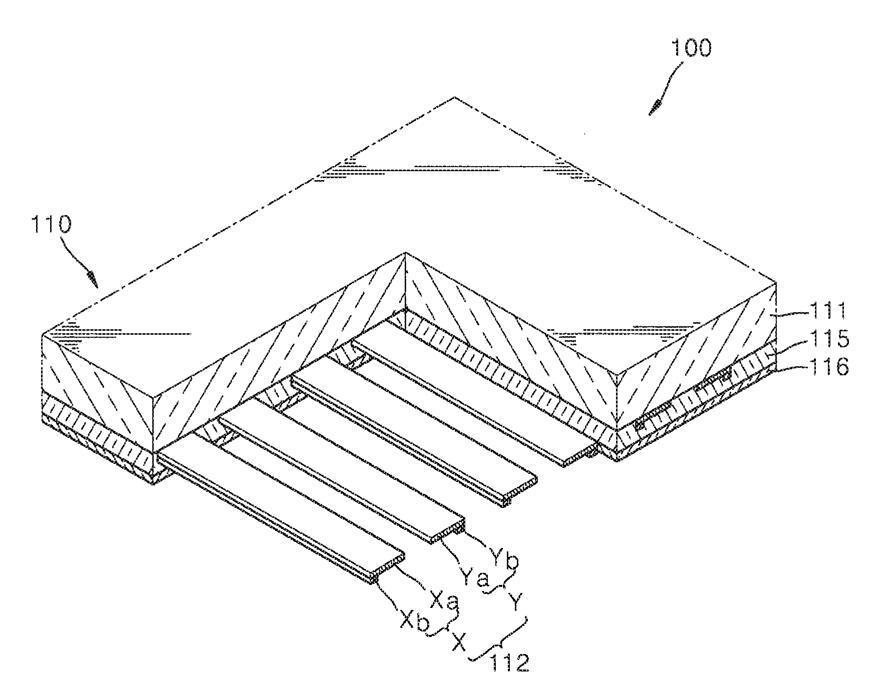
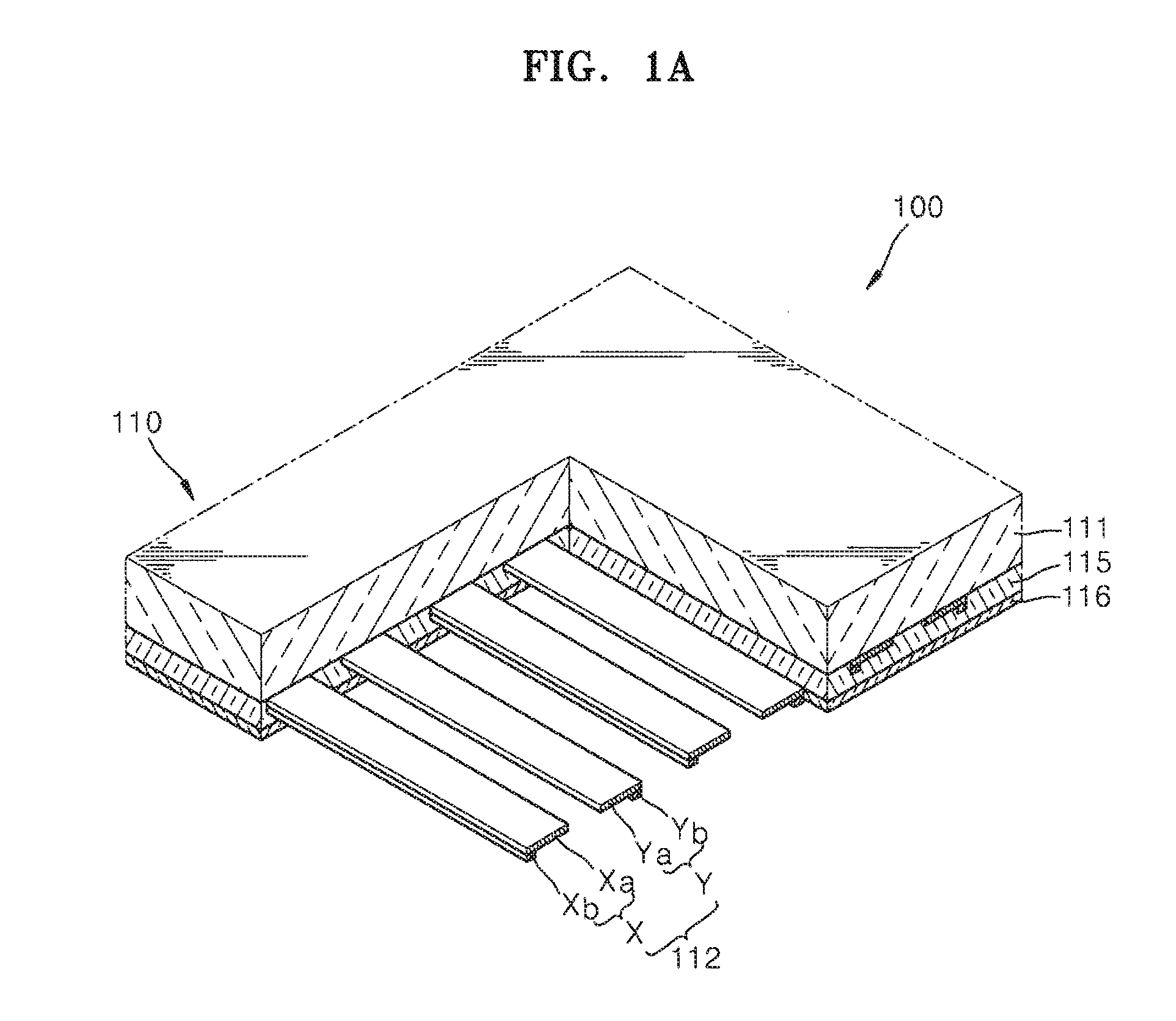
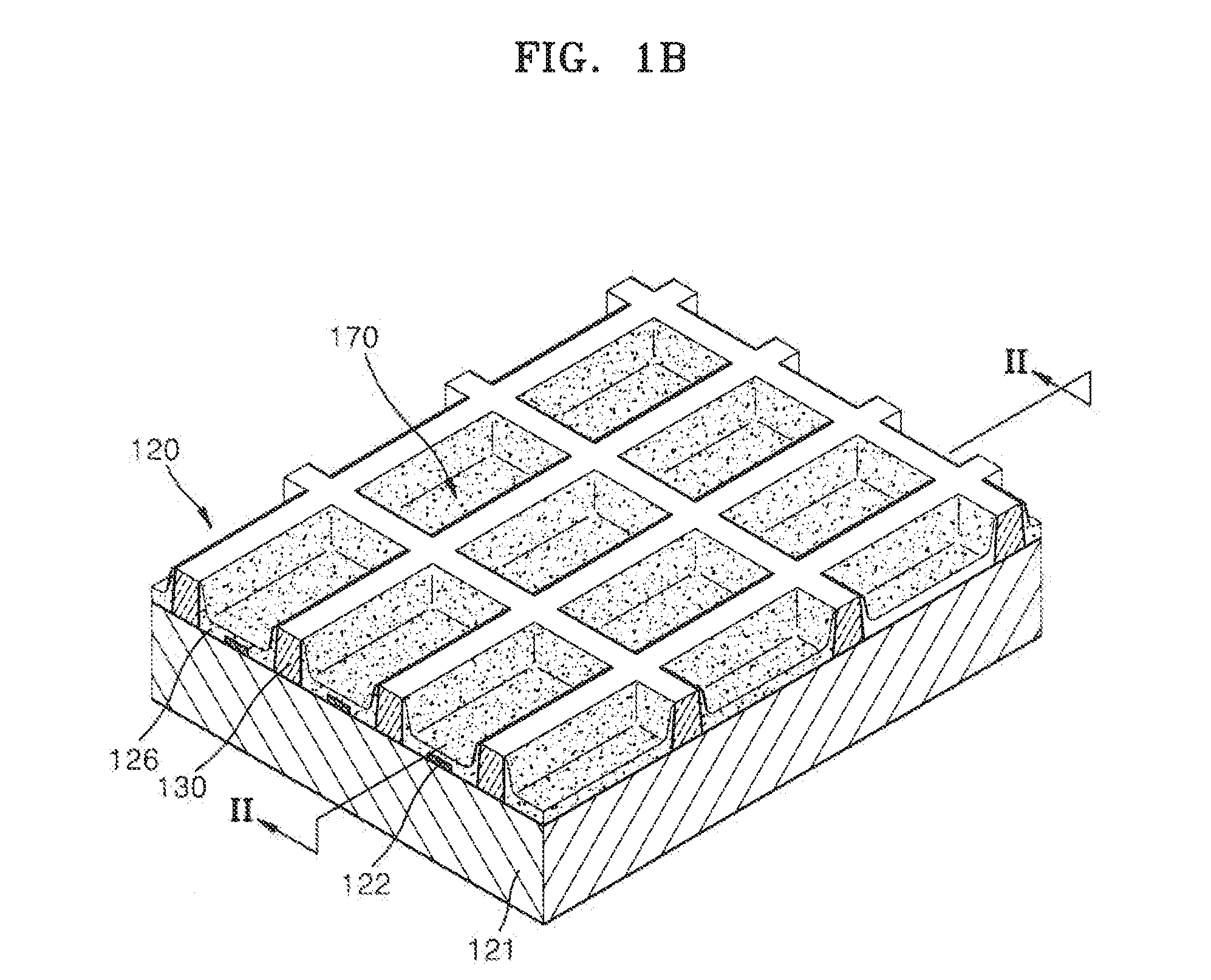
[0026]FIGS. 1A and 1B are perspective views schematically illustrating a plasma display panel 100 according to an ex embodiment of the present disclosure, and FIG. 2 is a cross-sectional view taken along a line II-II of FIGS. 1A. and 1B. Referring to FIGS. 1 and 2, the plasma display panel 100 includes a front panel 110 and an opposing rear panel 120. The front panel 110 includes a front substrate 111, discharge electrodes 112, a front dielectric layer 115, and a protective layer 116. The rear panel 120 includes a rear substrate 121, address barrier ribs 130, and a phosphor layer 126. A discharge gas is filled in a space ...


PUM


Abstract

A plasma display panel including: a front substrate an opposing rear substrate; barrier ribs to form discharge cells between the front rear substrates; discharge electrodes disposed on the front substrate; address electrodes disposed on the rear substrate; and a phosphor layer disposed inside the discharge cells, covering the address electrodes. The phosphor layer includes a phosphor mixed with an intercalation agent having a smaller particle size than the phosphor.

Description

CROSS-REFERENCE TO RELATED APPLICATION[0001]This application claims the benefit of Korean Patent Application No. 10-2009-0117067, filed on Nov. 30, 2009, in the Korean Intellectual Property Office, the disclosure of which is incorporated herein by reference.BACKGROUND[0002]1. Field[0003]One or more embodiments of the present disclosure relate to a plasma display panel and a method of manufacturing the same.[0004]2. Description of the Related Art[0005]Plasma display devices are flat panel display devices that display an image using plasma display panel to produce a gas discharge phenomenon. Plasma display devices have come into the spotlight as the next generation of large flat panel display devices, due to excellent display characteristics, such as, luminance, contrast, response speed, and viewing angle, and have thin profiles with large screen size.[0006]In a plasma display panel, a discharge electrode (display electrode) is formed on an inner surface of a front glass substrate, wh...

Claims


Application Information

Patent Timeline
IPC IPC(8): H01J61/42H01J9/00
CPCH01J9/227H01J11/42H01J11/12H01J2209/012
Inventor KIM, GI-YOUNG
Owner SAMSUNG SDI CO LTD
Why Eureka
Try Eureka