Pathogen and particle detector system and method

Active Publication Date: 2007-01-18
YAMATAKE HONEYWELL CO LTD
View PDF99 Cites 161 Cited by
  • Summary
  • Abstract
  • Description
  • Claims
  • Application Information

AI Technical Summary

Benefits of technology

[0033] This detector system is sensitive, inexpensive, and rugged enough for field deployment. Although the system does not necessarily always detect or identify an exact particle, it can provide a sensitive and cost effecti

Problems solved by technology

Weaponized anthrax spores are extremely dangerous because they can gain passage into the human lungs.
One problem with existing detectors or particle counters which, are designed for detection of scattered light is that the scattering signal must be extracted from the incident illumination light source signal.
Currently, conventionally designed laser particle counters are fragile and expensive, and unsuited to this application.
This is capable of detecting an aerosol concentration of five particles per liter of air, but involves expensive an

Method used


Image

  • Pathogen and particle detector system and method
  • Pathogen and particle detector system and method
  • Pathogen and particle detector system and method

Examples


Example

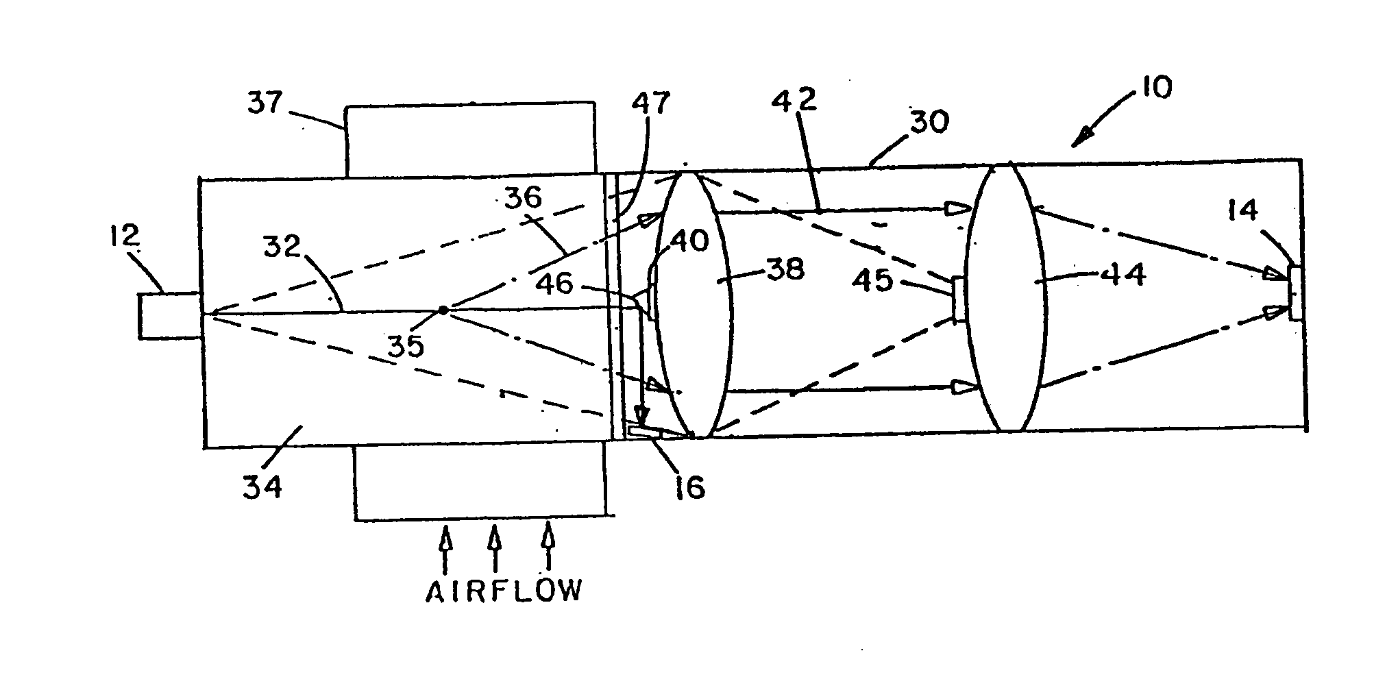
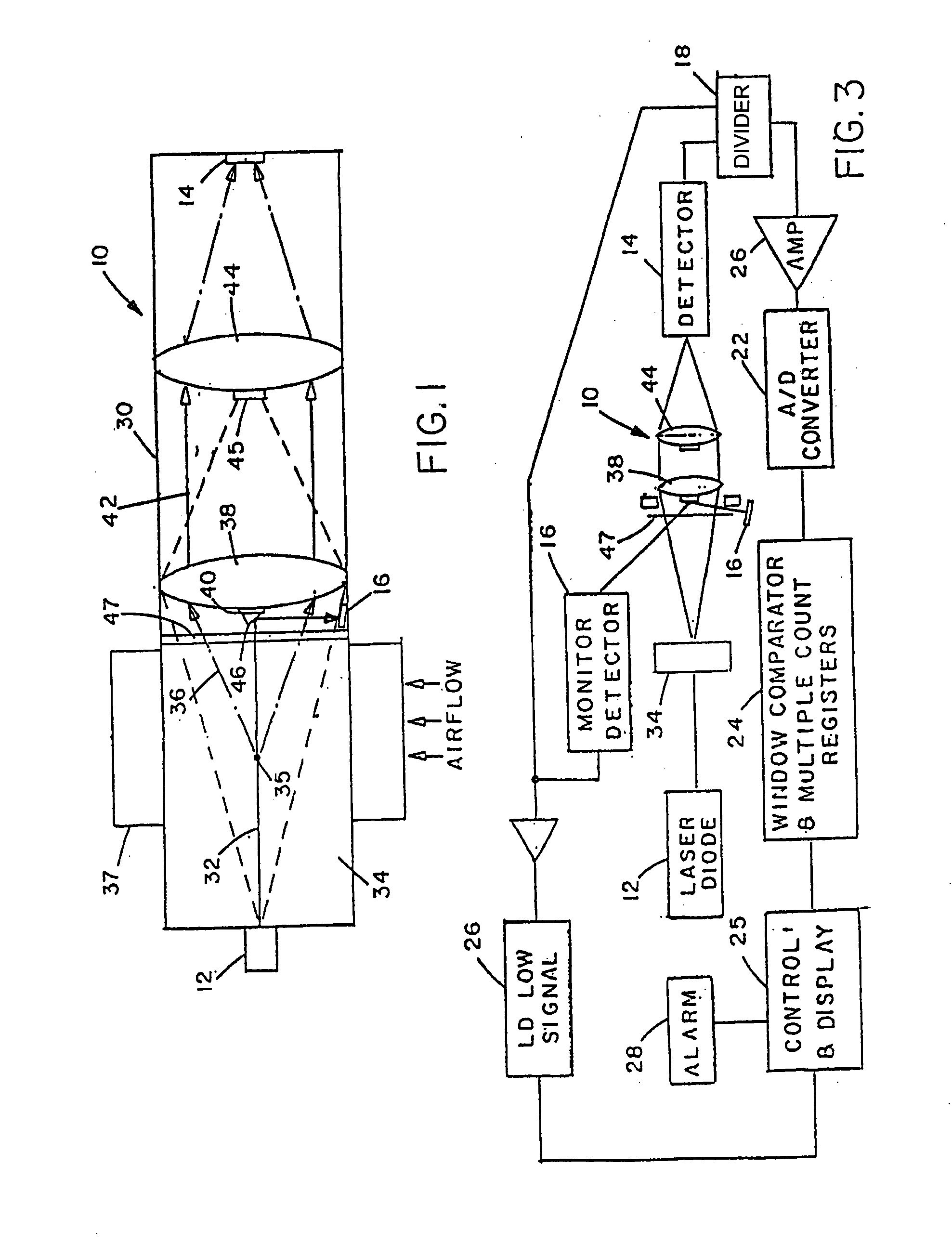
[0067] As illustrated in FIGS. 1 and 3, the first embodiment of the system basically comprises an optical unit 10, a laser diode or other light source 12 directing a collimated or nearly collimated light beam into the optical unit 10, a first photodetector 14 at the output of optical unit detecting light transmitted through the unit, a second photodetector 16 for detecting the light output of the laser diode, a signal divider 18 for dividing the output of photodetector 14 by the output of photodetector 16, an amplifier 26 connected to the output of differential amplifier 18, an analog to digital converter 22, a window comparator circuit 24, and a control and output display unit 25 connected to the output of circuit 24. A low signal detection circuit 26 is connected to the output of photodetector / monitor detector 16 which detects the laser diode power, and the output of circuit is also connected to control unit 25. An alarm device 28 is also connected to control unit 25. Control unit...


PUM


Abstract

A particle detector has a sample area of cross section no in excess of about 2 mm for containing environmental fluid, a light source on one side of the sample area for directing a collimated or nearly collimated beam of light through the sample air or water so that part of the light beam will be scattered by any particles present in the air or water while the remainder remains unscattered, and a beam diverting device on the opposite side of the sample area for diverting or blocking at least the unscattered portion of the beam of light and directing at least part of the scattered light onto a detector. The detector produces output pulses in which each pulse has a height proportional to particle size and a pulse height discriminator obtains the size distribution of airborne particles detected in the air or water sample at a given time from the detector output. The detector may also include a device for discriminating between biological agents and inorganic particles.

Description

CROSS REFERENCE TO RELATED APPLICATION [0001] This application claims priority to four copending U.S. provisional applications: Ser. No. 60 / 592,618, entitled, “Pathogen Detector System and Method,” filed Jul. 30, 2004; Ser. No. 60 / 592,619, entitled, “Particle Detector System and Method,” filed Jul. 30, 2004; Ser. No. 60 / 606,212, entitled, “Pathogen Detector System and Method,” filed Sep. 1, 2004; and Ser. No. 60 / 683,534, entitled, “Improvements in Pathogen Detector Systems,” filed May, 20, 2005. All four copending U.S. provisional applications are entirely incorporated herein by reference.FIELD OF THE INVENTION [0002] The present invention relates generally to a system and method for detecting airborne or waterborne particles, and more particularly to a system and method for detecting airborne or waterborne particles and classifying the detected particles by size. The invention has particular utility in detecting and classifying by size allergens and biological warfare agents in flu...

Claims


Application Information

Patent Timeline
IPC IPC(8): G01N15/02
CPCG01N15/0205G01N21/53G01N21/05G01N2015/0088H03K5/04G01N21/6486G01N15/02G01N15/00H02P8/00G01N21/00
Inventor JIANG, JIAN-PINGBABICO, JOHNMORRELL, MICHAEL
Owner YAMATAKE HONEYWELL CO LTD
Why Eureka
Try Eureka