
Optical communications apparatus and method compatible with electrical communications systems

a technology of optical communication and electrical communication system, applied in the direction of electrical apparatus, bidirectional transmission, fiber transmission, etc., can solve the problem that the optical communication protocol and the system using it typically require relatively complex hardware and softwar

Inactive Publication Date: 2007-01-18
PARKER HANNIFIN CORP
View PDF11 Cites 17 Cited by
  • Summary
  • Abstract
  • Description
  • Claims
  • Application Information

AI Technical Summary

Benefits of technology

[0016] Although the invention is shown and described with respect to one or more embodiments, it is evident that equivalents and modifications will occur to others skilled in the art. The present invention includes all such equivalents and modifications, and is limited only by the scope of the claims.

Problems solved by technology

These optical communications protocols and systems using them typically require relatively complex hardware and software.

Method used


Image

  • Optical communications apparatus and method compatible with electrical communications systems
  • Optical communications apparatus and method compatible with electrical communications systems
  • Optical communications apparatus and method compatible with electrical communications systems

Examples


Embodiment Construction

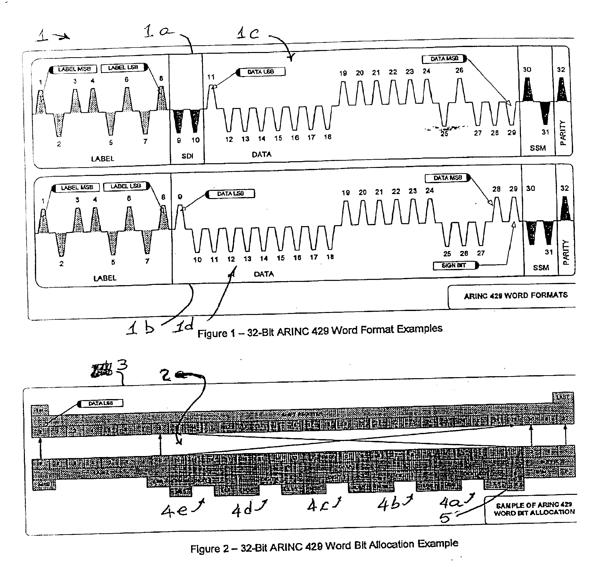
[0026] Referring, now, to the drawings, and initially to FIG. 1 and to the examples of the invention presented below with respect to the several drawing figures in which like reference numerals designate like parts in the several figures, the invention is presented with respect to maintaining the standard ARINC 429 data protocol of 32-bit words, an example of which is illustrated at 1, which contain nineteen (19) bits of data at 1a or twenty-one (21) bits of data at 1b. In addition to the nineteen (19) bits of data or twenty-one (21) bits of data 1c, 1d, respectively, each of the data words 1a, 1b also includes nine (9) label bits and additional status bits, parity bit, etc., as is conventional for ARINC 429 protocol data and which are indicated in the drawing of FIG. 1. Thus, FIG. 1 illustrates an example of the ARINC 429 data protocol for the electrical bits thereof. Each of the bits is represented by a positive voltage level or a negative voltage level, each relative to ground or...


PUM


Abstract

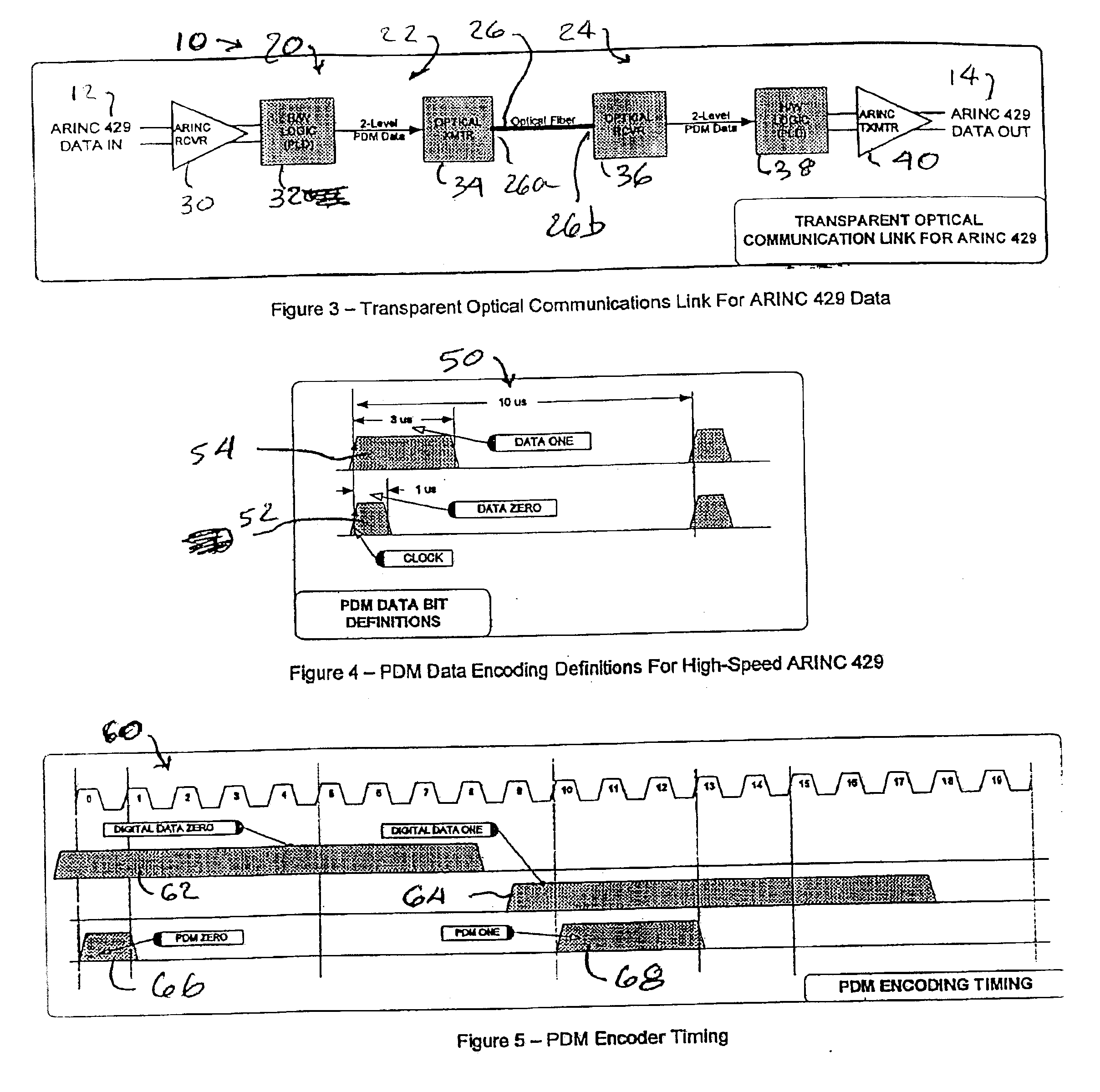
An optical communications link for an electrical communications system, e.g., an ARINC 429 protocol system, includes a first logic device to convert an input signal of a given level to a first electrical signal of a duration corresponding to such level, a first optical device (transmitter) presenting an optical signal of a duration corresponding to such first electrical signal, a second optical device (receiver) to convert the optical signal to a second electrical signal of a duration representative of the duration of the optical signal, an optical coupling between the optical devices, and a second logic device to convert the second electrical signal to an output electrical signal having a level representative of the duration of the optical signal. A communications system including electrical communications input and output devices, the optical and an optical communications link coupled between those devices. A method of coupling electrical signals includes converting or encoding electrical signals that are provided at multiple levels in an electrical communications system to optical signals that have a duration respectively representative of the corresponding electrical signal level, transmitting the optical signals, and decoding the optical signals. The converting / encoding and the decoding may be accomplished using hardware logic without the need for a processor and associated software.

Description

RELATED APPLICATIONS [0001] This application claims the benefit of U.S. Provisional Application No. 60 / 698,650 filed Jul. 12, 2005.FIELD OF THE INVENTION [0002] The present invention relates generally, as indicated, to optical communications apparatus and method compatible with electrical communications systems, and the invention relates to optical communications apparatus and method compatible with and substantially transparent to electrical communications systems used in aircraft, such as, for example the ARINC 429 standard electrical communications systems. BACKGROUND OF THE INVENTION [0003] Many optical communications protocols via fiber optics are well established. In the field of avionics, some of the standards covering optical communications include ARINC 629, ARINC 664 and ARINC 763; the latter two standards cover the use of optical Ethernet in aircraft, such as, for example, 100-Base FX and 1,000-Base FX. These optical communications protocols and systems using them typical...

Claims


Application Information

Patent Timeline
Patent Type & Authority Applications(United States)
IPC IPC(8): H04B10/00
CPCH04B10/12H04B10/2589
Inventor AUSTERLITZ, HOWARDBUETER, RONALDKORENSHTEIN, AVI
Owner PARKER HANNIFIN CORP
Learn More