
Perpendicular magnetic recording medium

a technology of perpendicular magnetic and recording medium, which is applied in the field of can solve the problems of affecting the improvement of the recording density of the perpendicular magnetic recording medium, affecting the accuracy of the perpendicular magnetic anisotropy, and affecting the accuracy of the perpendicular magnetic recording layer. , to achieve the effect of high reliability

Inactive Publication Date: 2007-01-18
KIKITSU AKIRA +1
View PDF7 Cites 10 Cited by
  • Summary
  • Abstract
  • Description
  • Claims
  • Application Information

AI Technical Summary

Benefits of technology

The present invention provides a perpendicular magnetic recording medium with high reliability and performance. The medium includes a substrate, a soft magnetic underlayer, arrayed soft magnetic dots, and a ferro-magnetic recording layer. The soft magnetic dots serve to attract magnetic flux even if the position of the magnetic pole of the head is deviated from the recording region, improving recording performance. The medium can also have a reduced flying height of the magnetic head and suppress fluctuation of magnetization transition extending over a ferromagnetic recording region, resulting in high-density magnetic recording.

Problems solved by technology

However, the problem of the thermal fluctuation inhibits the improvement in the recording density of the perpendicular magnetic recording medium.
As a result, it becomes problematic that the magnetic characteristics of the ferromagnetic recording layer are damaged; in particular, the magnitude and the direction of the perpendicular magnetic anisotropy are deteriorated.
However, it is difficult to lower the flying height in the patterned media, which has been irregularly processed, unlike the ordinary medium having a substantially flat surface.
However, it is difficult to locate the magnetic head accurately at the position of the individual ferromagnetic dot.
Where the position of the magnetic pole of the write head deviates greatly from the ferromagnetic dot, though a slight positional deviation is allowable, it is impossible to apply a recording magnetic field to a part of the ferromagnetic dot, with the result that effective recording magnetic field strength is lowered so as to render the recording efficiency poor.
Therefore, an appreciably large deviation between the magnetic head and the ferromagnetic dot is not allowable.
As described above, the problem that processing deteriorates the magnetic characteristics of the ferromagnetic recording layer was inherent in the conventional patterned media.
Also, the conventional patterned media was defective in that it was difficult to lower the flying height of the magnetic head, and that the allowable positional deviation between the write / read head and the ferromagnetic dot of the recording layer is small.

Method used


Image

  • Perpendicular magnetic recording medium
  • Perpendicular magnetic recording medium
  • Perpendicular magnetic recording medium

Examples


first embodiment

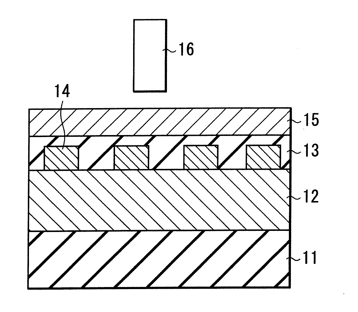
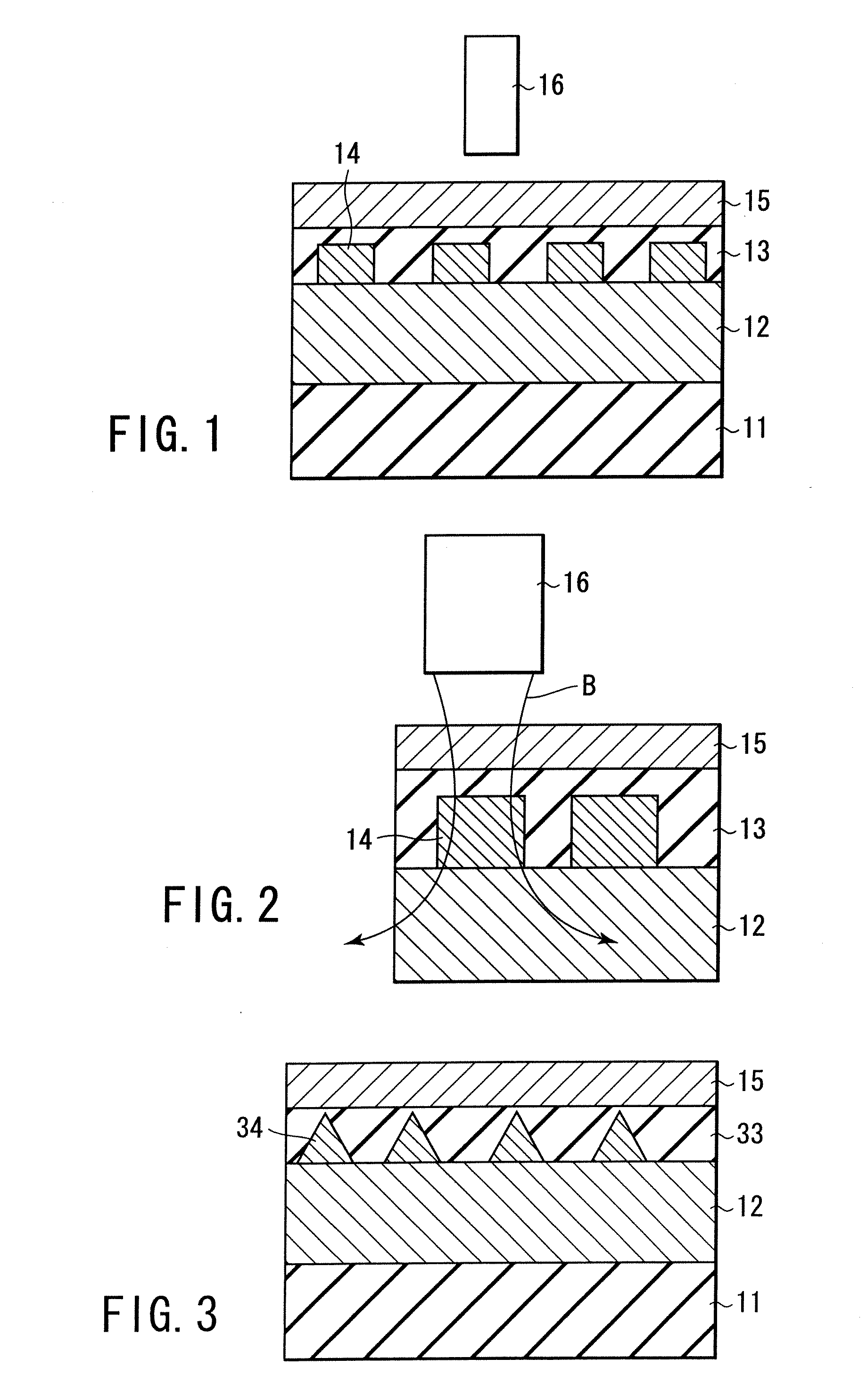
[0032]FIG. 1 is a cross-sectional view showing the structure of a perpendicular magnetic recording medium according to a first embodiment of the present invention. As shown in FIG. 1, the perpendicular magnetic recording medium comprises a substrate 11, a soft magnetic underlayer 12 formed on the substrate 11, arrayed soft magnetic dots 14 formed on the soft magnetic underlayer 12, a ferromagnetic recording layer 15 formed on the soft magnetic dots 14 and having magnetic anisotropy in a direction perpendicular to the surface of the substrate 11. In the embodiment shown in the drawing, an intermediate layer 13 is embedded between adjacent soft magnetic dots 14 and is interposed between the soft magnetic dots 14 and the ferromagnetic recording layer 15. The upper surface of the intermediate layer 13 is planarized so as to lower the flying height of the head. It is desirable for the flatness to be 10 nm or less, preferably 5 nm or less, and more preferably 3 nm or less in terms of the ...

second embodiment

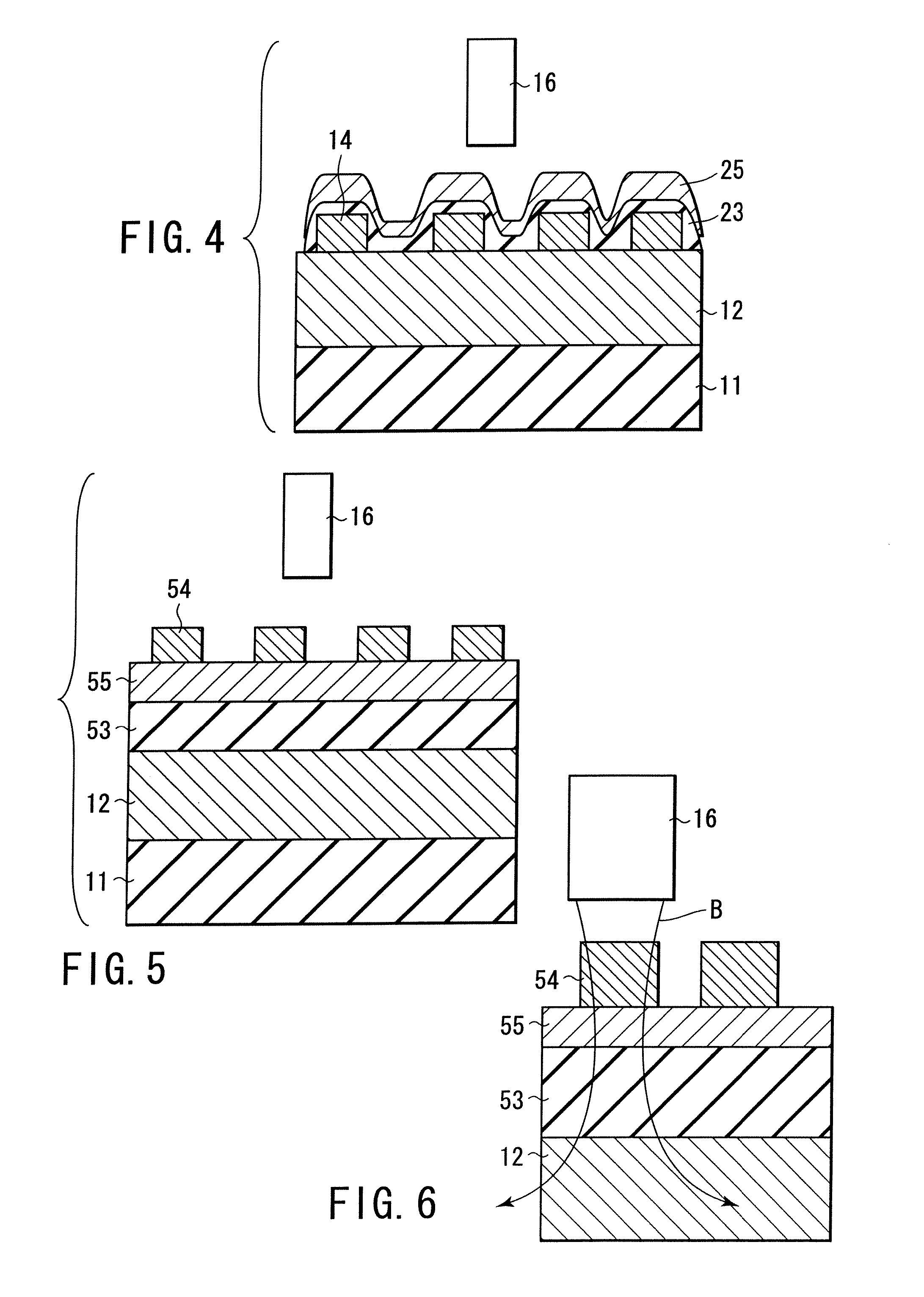
[0058]FIG. 5 is a cross-sectional view showing the structure of the perpendicular magnetic recording medium according to a second embodiment of the present invention. As shown in the drawing, the perpendicular magnetic recording medium comprises a substrate 11, a soft magnetic underlayer 12 formed on the substrate 11, a nonmagnetic intermediate layer 53 formed on the soft magnetic underlayer 12, a ferromagnetic recording layer 55 formed on the nonmagnetic intermediate layer 53 and having magnetic anisotropy in a direction perpendicular to the upper surface of the substrate 11, and arrayed soft magnetic dots 54 formed on the ferromagnetic recording layer 55. Incidentally, the portions equal to those in FIG. 1 are denoted by the same reference numerals.

[0059] In the perpendicular magnetic recording medium according to the second embodiment, the soft magnetic dots 54 are formed on the ferromagnetic recording layer 55. The function performed by the particular perpendicular magnetic rec...

third embodiment

[0066]FIG. 9 is a cross-sectional view showing the structure of a perpendicular magnetic recording medium according to a third embodiment of the present invention. As shown in the drawing, the perpendicular magnetic recording medium a substrate 11, a soft magnetic underlayer 12 formed on the substrate 11, a nonmagnetic layer 53 formed on the soft magnetic underlayer 12, arrayed ferromagnetic recording regions 75a defined by grooves 75b engraved in a ferromagnetic layer formed on the nonmagnetic layer 53, each ferromagnetic recording region 75a having magnetic anisotropy in a direction perpendicular to a surface of the substrate 11, and arrayed soft magnetic dots 54 formed on the respective ferromagnetic recording regions 75a.

[0067] In the perpendicular magnetic recording medium according to the third embodiment, the surface of the ferromagnetic recording layer 75 is processed so as to form the grooves 75b, thereby forming ferromagnetic recording regions 75a. By processing a part of...


PUM

PropertyMeasurementUnit
thicknessaaaaaaaaaa
thicknessaaaaaaaaaa
roughnessaaaaaaaaaa

Abstract

A perpendicular magnetic recording medium has a substrate, a soft magnetic underlayer formed on the substrate, arrayed soft magnetic dots formed on the soft magnetic underlayer, and a ferromagnetic recording layer formed on the soft magnetic dots and having magnetic anisotropy in a direction perpendicular to a surface of the substrate.

Description

CROSS-REFERENCE TO RELATED APPLICATIONS [0001] This application is based upon and claims the benefit of priority from the prior Japanese Patent Application No. 2002-282439, filed Sep. 27, 2002, the entire contents of which are incorporated herein by reference. BACKGROUND OF THE INVENTION [0002] 1. Field of the Invention [0003] The present invention relates to a perpendicular magnetic recording medium capable of achieving high-density magnetic recording. [0004] 2. Description of the Related Art [0005] For performing high-density magnetic recording, it is necessary to reduce the size of magnetic domains, each of which is a recording unit of information. In the perpendicular magnetic recording medium that is generally used nowadays, information is recorded in a magnetic thin film containing magnetically disrupted magnetic grains. In order to reduce the size of the magnetic domains and to discriminate boundaries thereof for the high-density magnetic recording, it is necessary to reduce ...

Claims


Application Information

Patent Timeline
Patent Type & Authority Applications(United States)
IPC IPC(8): G11B5/66G11B5/667G11B5/65G11B5/73G11B5/738G11B5/855
CPCG11B5/667Y10T428/24355G11B5/855
Inventor KIKITSU, AKIRAKAMATA, YOSHIYUKI
Owner KIKITSU AKIRA
Learn More