Perpendicular magnetic recording medium

a technology of perpendicular magnetic and recording medium, which is applied in the field of can solve the problems of affecting the improvement of the recording density of the perpendicular magnetic recording medium, affecting the accuracy of the perpendicular magnetic anisotropy, and affecting the accuracy of the perpendicular magnetic recording layer. , to achieve the effect of high reliability

Inactive Publication Date: 2006-11-28
KK TOSHIBA
View PDF8 Cites 29 Cited by
  • Summary
  • Abstract
  • Description
  • Claims
  • Application Information

AI Technical Summary

Benefits of technology

[0011]An object of the present invention is to provide a perpendicular magnetic recording medium having a large allowable positional deviation between the write / read head and the recording region in the recording layer and having high reliability.

Problems solved by technology

However, the problem of the thermal fluctuation inhibits the improvement in the recording density of the perpendicular magnetic recording medium.
As a result, it becomes problematic that the magnetic characteristics of the ferromagnetic recording layer are damaged; in particular, the magnitude and the direction of the perpendicular magnetic anisotropy are deteriorated.
However, it is difficult to lower the flying height in the patterned media, which has been irregularly processed, unlike the ordinary medium having a substantially flat surface.
However, it is difficult to locate the magnetic head accurately at the position of the individual ferromagnetic dot.
Where the position of the magnetic pole of the write head deviates greatly from the ferromagnetic dot, though a slight positional deviation is allowable, it is impossible to apply a recording magnetic field to a part of the ferromagnetic dot, with the result that effective recording magnetic field strength is lowered so as to render the recording efficiency poor.
Therefore, an appreciably large deviation between the magnetic head and the ferromagnetic dot is not allowable.
As described above, the problem that processing deteriorates the magnetic characteristics of the ferromagnetic recording layer was inherent in the conventional patterned media.
Also, the conventional patterned media was defective in that it was difficult to lower the flying height of the magnetic head, and that the allowable positional deviation between the write / read head and the ferromagnetic dot of the recording layer is small.

Method used


Image

  • Perpendicular magnetic recording medium
  • Perpendicular magnetic recording medium
  • Perpendicular magnetic recording medium

Examples


example 1

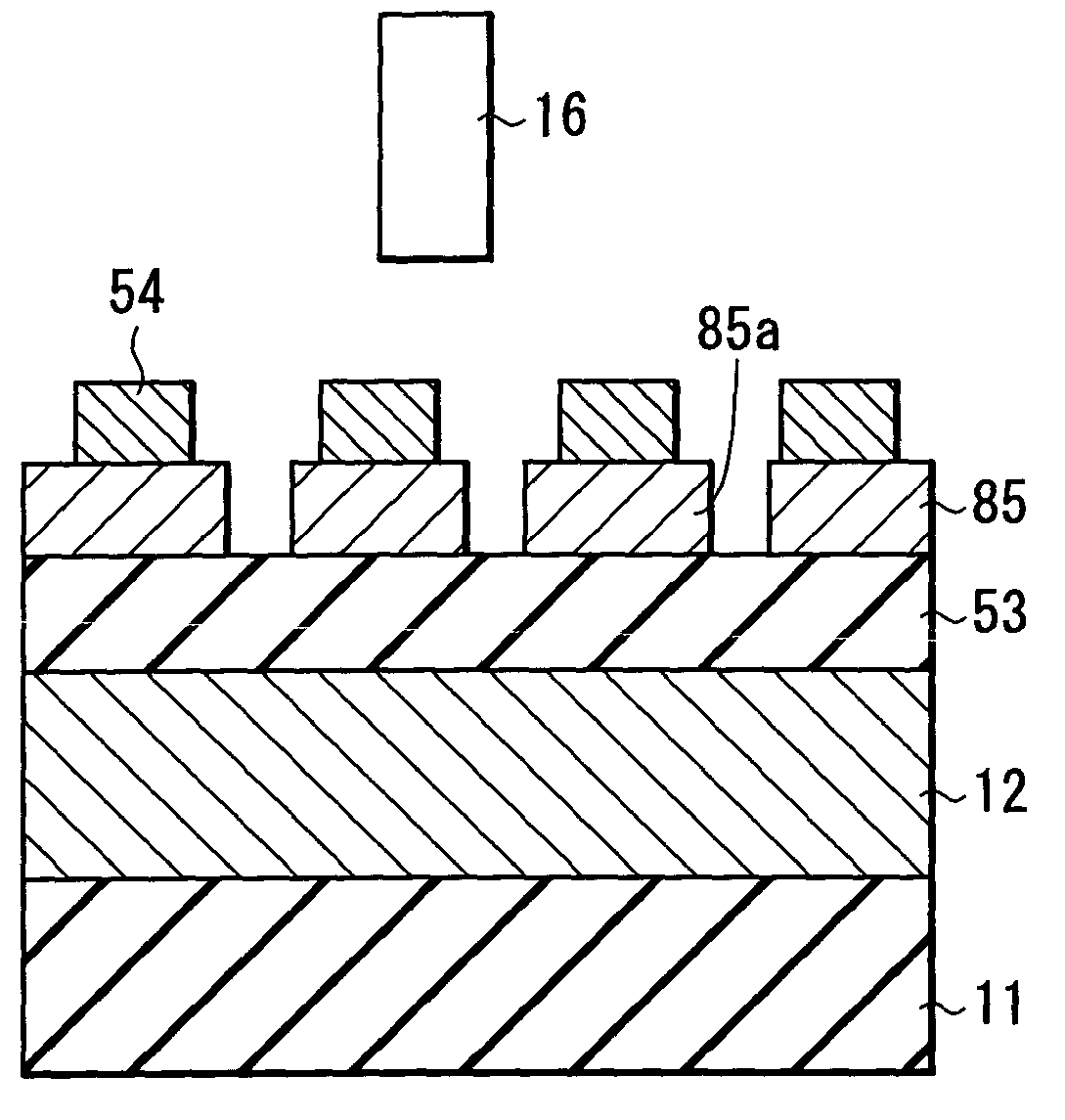
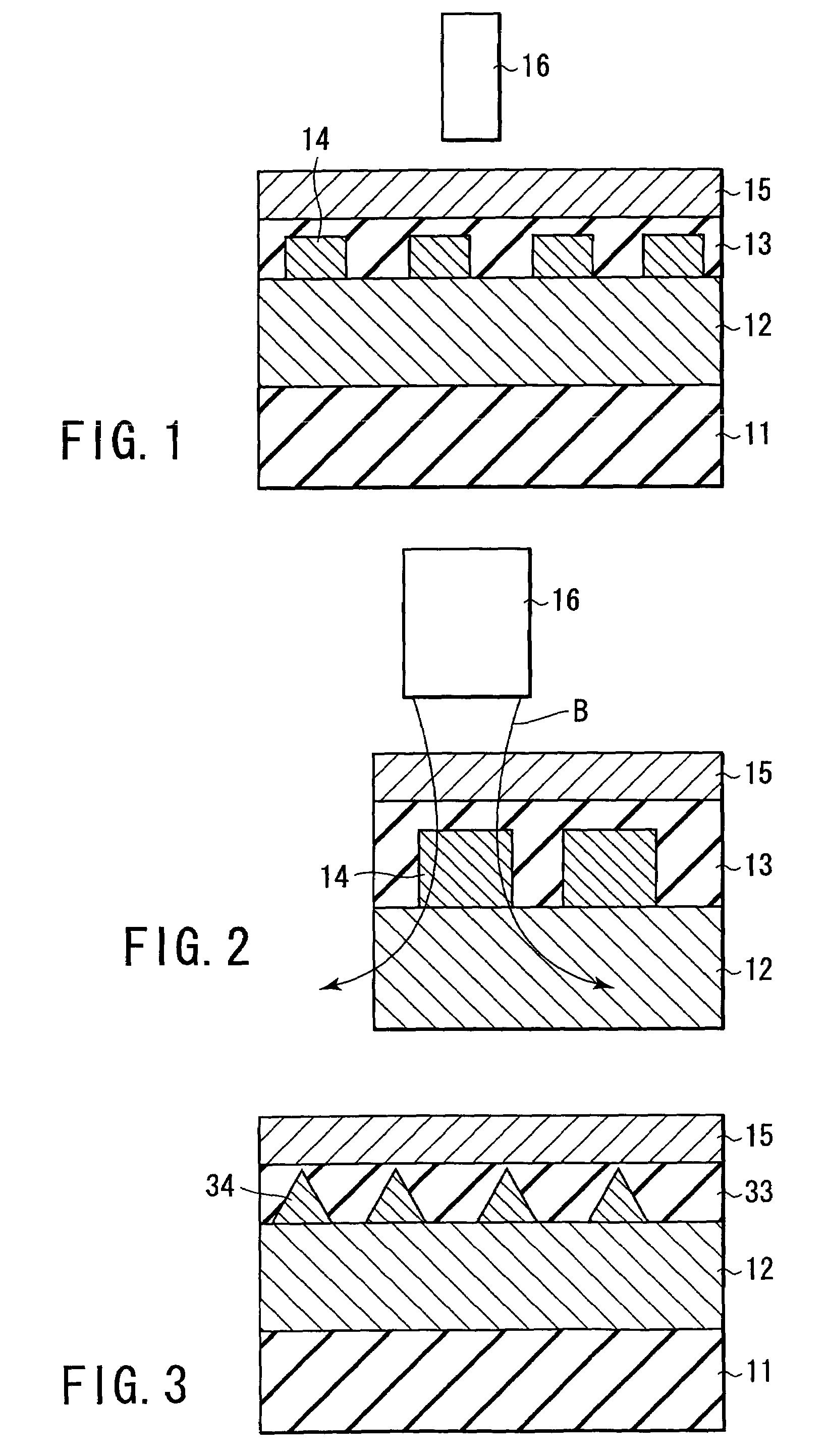
[0076]FIG. 1 is a cross-sectional view schematically showing the structure of the perpendicular magnetic recording medium for this Example. The perpendicular magnetic recording medium was manufactured as follows. In the first step, a NiAl film (not shown) having a thickness of 10 nm, a soft magnetic underlayer 12 of a FeSiAl film having a thickness of 100 nm, and a carbon film (not shown) having a thickness of 2 nm were successively deposited by sputtering on a glass disk substrate 11 having a diameter of 2.5 inches. The NiAl film was intended to control the orientation of the FeSiAl film formed thereon. Then, a resist was applied thereon, followed by forming a resist mask, in which square openings each sized at 40 nm-square were arrayed at an interval of 40 nm in the circumferential direction of the disk, by the technology similar to ordinary lithography.

[0077]In the next step, a CoZrNb film, which was used for forming the soft magnetic dots 14, was deposited in a thickness of 30 n...

example 2

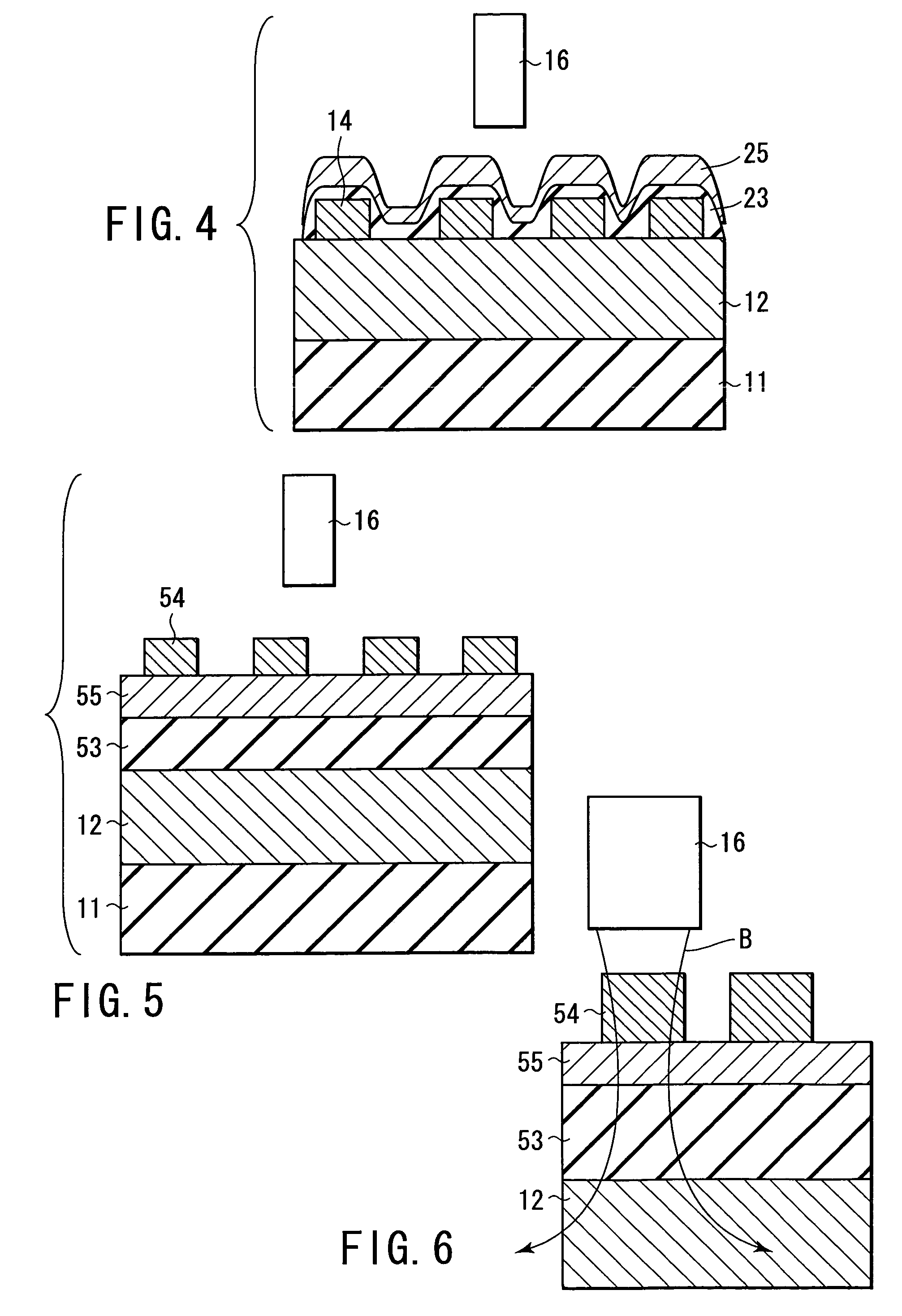
[0080]FIG. 4 is a cross-sectional view schematically showing the structure of the perpendicular magnetic recording medium for this Example. The perpendicular magnetic recording medium was manufactured as follows. First, a soft magnetic underlayer 12 of a multi-layered structure was deposited on a glass substrate disk 11 having a diameter of 2.5 inches by repeating ten times the formation of a unit consisting of a Fe film having a thickness of 8 nm and a carbon film having a thickness of 2 nm by sputtering. Then, a CoZrNb film having a thickness of 30 nm, which was to be processed into soft magnetic dots 14, and a carbon film having a thickness of 1 nm (not shown) were successively deposited. Further, the CoZrNb film and the carbon film were processed by FIB (Focused Ion Beam) so as to form a pattern in which oblongs each sized at 30 nm×20 nm were repeatedly formed at an interval of 30 nm, followed by depositing an Si—N intermediate layer 23 in a thickness of 10 nm. Then, a unit cons...

example 3

[0083]FIG. 3 is a cross-sectional view schematically showing the structure of the perpendicular magnetic recording medium for this Example. The perpendicular magnetic recording medium was manufactured as follows. In the first step, a NiAl film (not shown) having a thickness of 10 nm, a FeSiAl film having a thickness of 100 nm, which was to be used as a soft magnetic underlayer 12 and to be processed into soft magnetic dots 34, and a Pt film (not shown) having a thickness of 2 nm were formed successively by sputtering on a glass disk substrate 11 having a diameter of 2.5 inches. The NiAl film was intended to control the orientation of the FeSiAl film formed thereon.

[0084]In the next step, a resist was applied thereon, followed by processing the resist by pressing a stamper prepared in advance, which had a concentric groove pattern of a groove width of 150 nm, against the resist so as to form concentric grooves in the resist. Then, a PS-PMMA diblock copolymer was applied thereon, foll...


PUM

PropertyMeasurementUnit
thicknessaaaaaaaaaa
roughnessaaaaaaaaaa
flatnessaaaaaaaaaa

Abstract

A perpendicular magnetic recording medium has a substrate, a soft magnetic underlayer formed on the substrate, arrayed soft magnetic dots formed on the soft magnetic underlayer, and a ferromagnetic recording layer formed on the soft magnetic dots and having magnetic anisotropy in a direction perpendicular to a surface of the substrate.

Description

CROSS-REFERENCE TO RELATED APPLICATIONS[0001]This application is based upon and claims the benefit of priority from the prior Japanese Patent Application No. 2002-282439, filed Sep. 27, 2002, the entire contents of which are incorporated herein by reference.BACKGROUND OF THE INVENTION[0002]1. Field of the Invention[0003]The present invention relates to a perpendicular magnetic recording medium capable of achieving high-density magnetic recording.[0004]2. Description of the Related Art[0005]For performing high-density magnetic recording, it is necessary to reduce the size of magnetic domains, each of which is a recording unit of information. In the perpendicular magnetic recording medium that is generally used nowadays, information is recorded in a magnetic thin film containing magnetically disrupted magnetic grains. In order to reduce the size of the magnetic domains and to discriminate boundaries thereof for the high-density magnetic recording, it is necessary to reduce the size of...

Claims


Application Information

Patent Timeline
Patent Type & Authority Patents(United States)
IPC IPC(8): G11B5/66G11B5/70G11B5/667G11B5/65G11B5/73G11B5/738G11B5/855
CPCG11B5/667G11B5/855Y10T428/24355
Inventor KIKITSU, AKIRAKAMATA, YOSHIYUKI
Owner KK TOSHIBA
Why Eureka
Try Eureka