Lingual bracket

a lingual bracket and lingual side technology, applied in the field of lingual brackets, can solve the problems of very low risk of root resorption, and achieve the effects of low directional force, increased force, and very low height of lingual side brackets

Inactive Publication Date: 2007-01-18
DENTAURUM J P WINKELSTROETER
View PDF8 Cites 14 Cited by
  • Summary
  • Abstract
  • Description
  • Claims
  • Application Information

AI Technical Summary

Benefits of technology

[0025] The slot of the side tooth bracket has a slot base and two slot walls protruding from the latter. It is advantageous here if the slot walls are vertically aligned in the position of use of the side tooth bracket. Compared with the slot walls of a preferred embodiment of the brackets for the front and canine teeth, the slot walls of the side tooth bracket are consequently turned by 90°. This has the advantage that the height of the side tooth brackets on the lingual side can be kept very low, since the longer side of the slots extends substantially parallel to the bracket base. The placement of the archwire can be observed well from the occlusal side.
[0026] Round or cross-sectionally square archwires are used for the bracket system according to the invention. Given the same diameter of round wires or the same side length of square wires, such as the same shorter side length of rectangular wires, round and square wires have the advantage that relatively low directional forces are produced, since rectangular wires exert greater forces on account of their greater axial moment of inertia. It has been found that the exertion of rather lower directional forces is of advantage for the success of an orthodontic treatment for correcting the position of misaligned teeth, so that an improved position of the teeth can be achieved within a relatively short treatment time while the inconvenience for the patient is kept as little as possible.
[0027] In the case of bracket systems comprising only horizontally aligned slots, cross-sectionally rectangular archwires are usually used in the course of treatment. These are disti...

Problems solved by technology

In particular, forces of torsion and angulation can easily be...

Method used


Image

  • Lingual bracket
  • Lingual bracket
  • Lingual bracket

Examples


Embodiment Construction

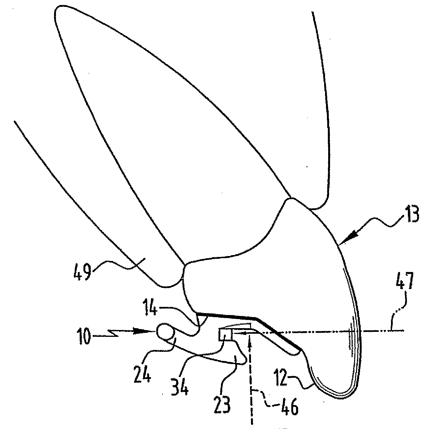
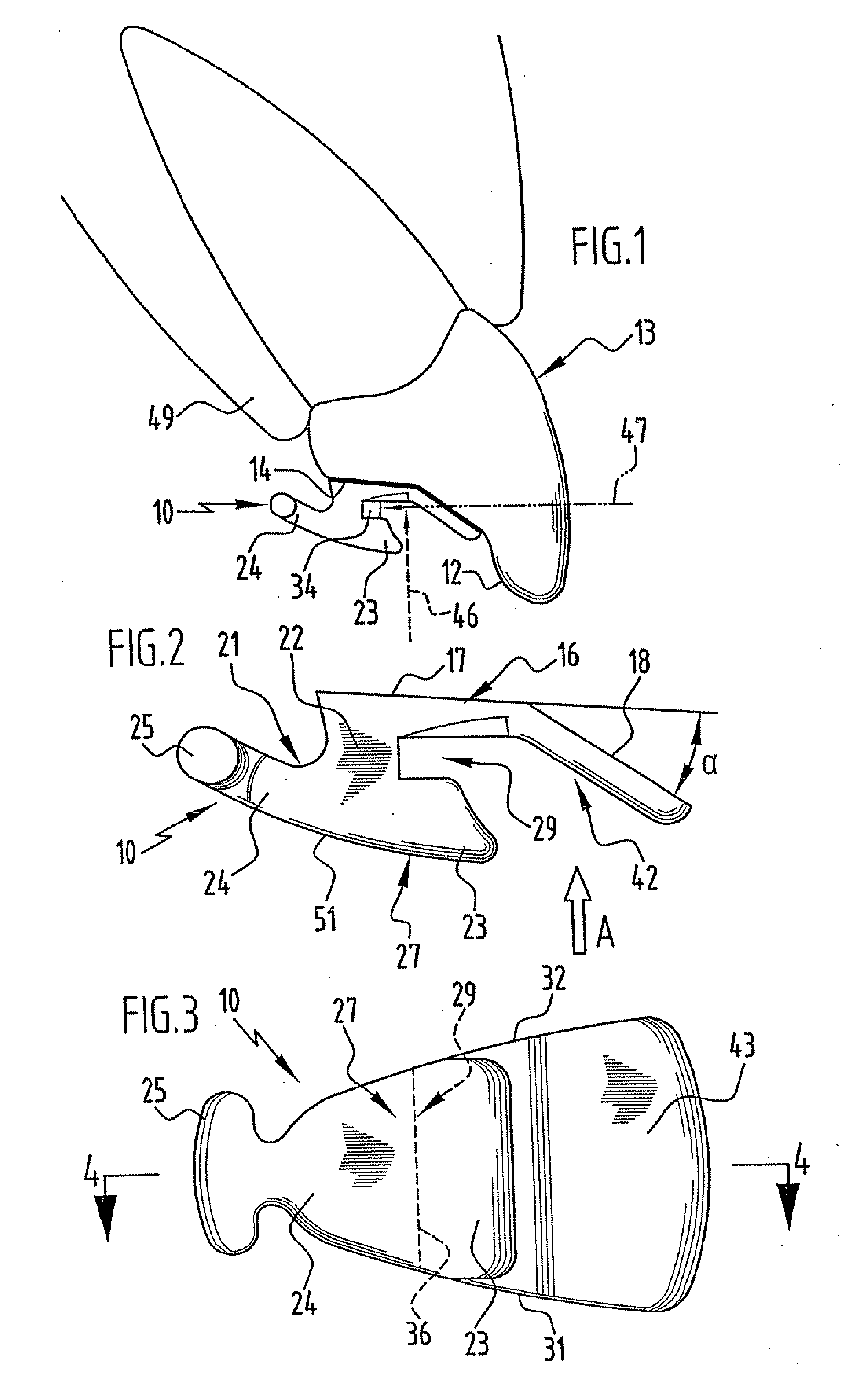
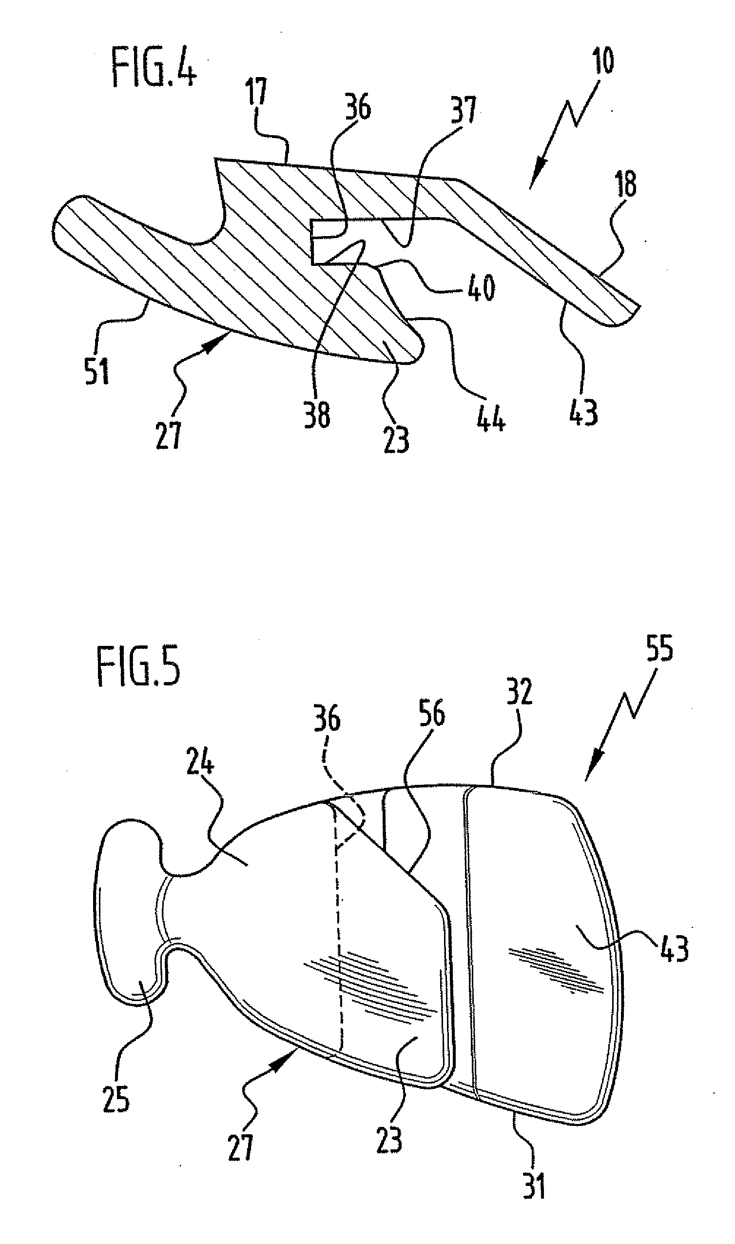
[0042] FIGS. 1 to 4 illustrate a bracket 10 according to the invention, which can be secured on the lingual side 12 of an upper jaw front tooth 13 by means of an adhesive 14. As revealed particularly clearly by FIGS. 2 and 4, the bracket 10 comprises a bracket base 16, which can be secured on the lingual side 12 and has a first abutting surface region 17 and a second abutting surface region 18, which are in each case of a planar configuration and are aligned at an angle a of approximately 30° in relation to one another. On the side away from the abutting surface region 17, the bracket base 16 is adjoined by a bracket body 21, which is of a substantially T-shaped configuration and has a web 22, which protrudes from the bracket base 16 on the occlusal side and the free end region of which is adjoined by a first wing 23, directed toward the second abutting surface region 18, and a second wing 24, directed away from said region. The second wing 24 carries at its free end a small T-shape...


PUM


Abstract

The invention relates to a lingual bracket for correcting the position of teeth, comprising a bracket base, which can be secured on the lingual side to a front or canine tooth, and comprising a bracket body, the bracket having a slot, which extends in the mesial-distal direction, delimited on the lingual side as well as on the gingival and occlusal sides, and which is intended for accommodating an archwire. In order to develop the bracket in such a way that an archwire can be easily inserted into the slot, by which even relatively small directional forces may be reproducibly exerted on the tooth and the risk of root resorption can be kept low, the slot is delimited on the gingival side by the bracket base and on the occlusal and lingual sides by the bracket body. Furthermore, a bracket system comprising a front or canine tooth bracket of this type and comprising a side tooth bracket is provided.

Description

CROSS-REFERENCE TO RELATED APPLICATIONS [0001] This application is a continuation of international application number PCT / EP2005 / 001713 filed on Feb. 18, 2005. [0002] The present disclosure relates to the subject matter disclosed in international application number PCT / EP2005 / 001713 of Feb. 18, 2005 and German application number 10 2004 009 916.2 of Feb. 20, 2004, which are incorporated herein by reference in their entirety and for all purposes.BACKGROUND OF THE INVENTION [0003] The invention relates to a lingual bracket for correcting the position of teeth, comprising a bracket base, which can be secured on the lingual side to a front or canine tooth, and comprising a bracket body, which protrudes from the bracket base, the bracket having a slot, which extends in the mesial-distal direction, is delimited on the lingual side as well as on the gingival and occlusal sides, and which is intended for accommodating an archwire. [0004] In order to correct positions of misaligned teeth in ...

Claims


Application Information

Patent Timeline
IPC IPC(8): A61C3/00A61C7/14
CPCA61C7/145A61C7/14
Inventor SOREL, OLIVIER
Owner DENTAURUM J P WINKELSTROETER
Why Eureka
Try Eureka