Dynamic spinal stabilization system

a spinal column and dynamic technology, applied in the field of dynamic spinal column stabilization system, can solve the problems of achieve the effect of reducing the loss of patient activity and reducing the flexibility of the spinal column

Inactive Publication Date: 2007-01-18
MEDICAL DEVICE CONCEPTS
View PDF48 Cites 294 Cited by
  • Summary
  • Abstract
  • Description
  • Claims
  • Application Information

AI Technical Summary

Benefits of technology

[0005] Therefore, in accordance with the present invention there is a posterior dynamic spinal stabilization system that is intended, for example, for the thoracic, cervical or lumbar sections of the spinal column and which provides a positive, yet flexible means of stabilizing the posterior of the spinal column. The stabilization system of the present invention can, therefore, allow the spinal column to regain its natural motion, that is, the present system can allow the spinal column to move with ranges of natural motion such as, preferably, movement in rotation to range from about greater than 0 to about 30 degrees, in medial / lateral motion in the range from about greater than 0 to about 45 degrees and for anterior / posterior (flexion / extension) in the range from about greater than 0 to about 120 degrees and, more preferably, movement in medial / lateral motion in the range from about greater than 0 to about 5 degrees and for anterior / posterior (flexion / extension) in the range from about greater than 0 to about 12 degrees. The present stabilization system can be used where there is a natural or artificial disc intermediate adjacent vertebrae, where there is a fusion cage or even where a spacer, including a multi-axial spacer, is utilized.
[0010] The aforedescribed flexible shafts have the added 
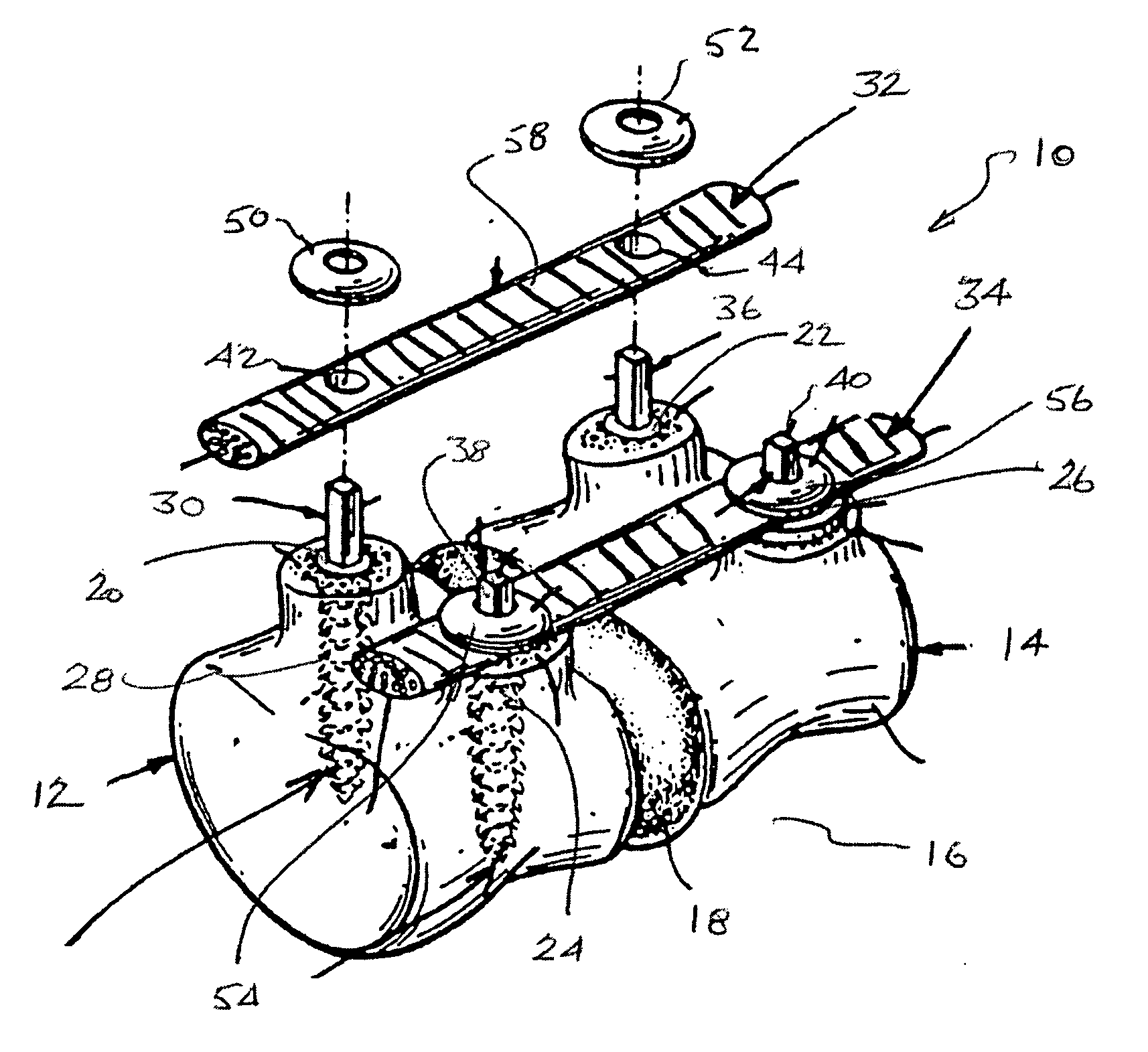
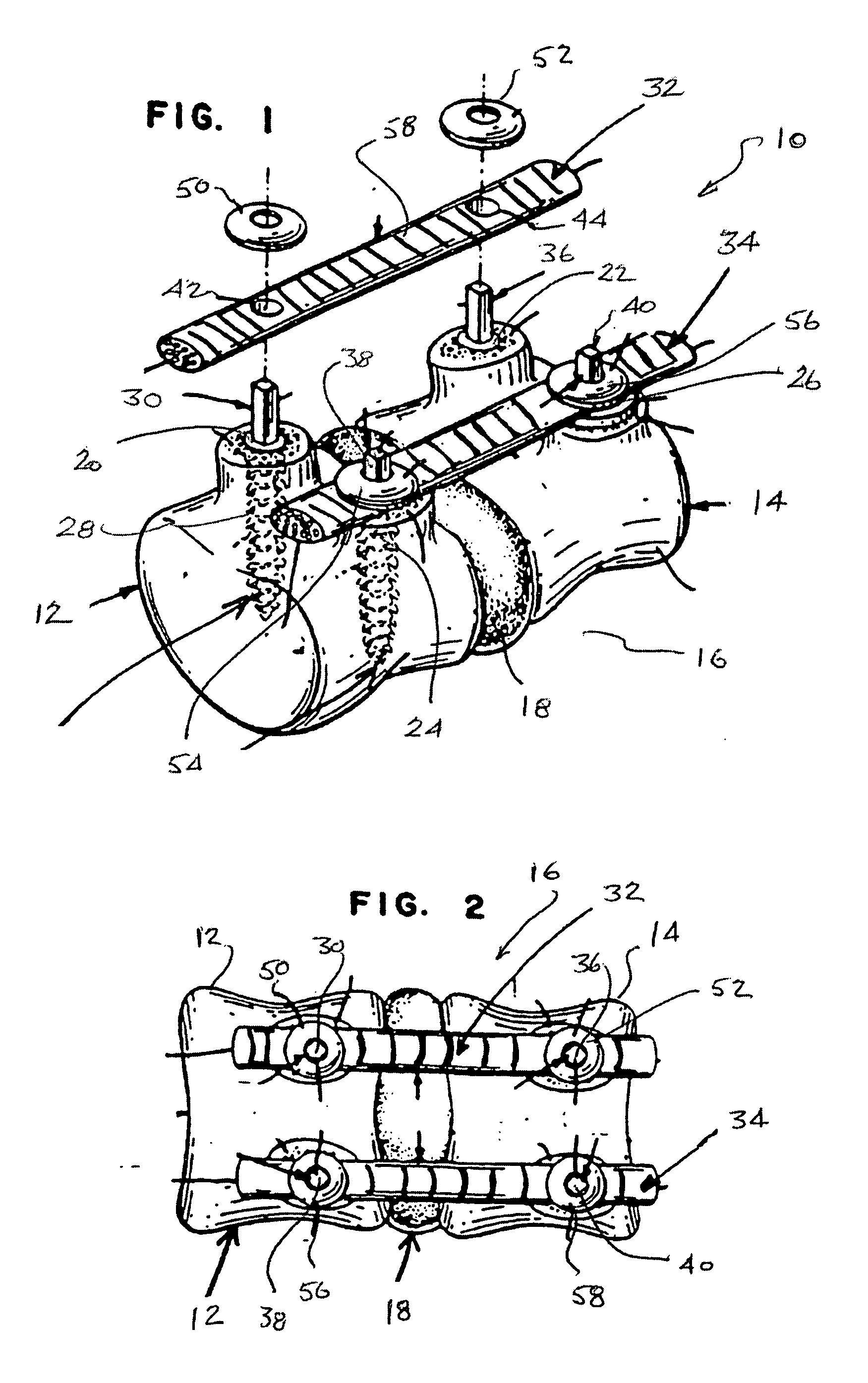
advantage in that the degree of flexibility can be designed into the particular flexible shaft, that is, the flexibility of the shaft can be designed so as to be predetermined by selecting among a number of parameters, such as but not limited to changing the spacing of the slots, selecting the material for making the flexible shaft or changing the cross section of the shaft and any one or more of those selections can be made to design into the flexible shaft, the flexibility that is desired in the ultimate stabilization system. Accordingly, the amount of flexibility of the stabilization system can be designed in accordance with the needs of the particular spinal column. In addition, with a monolithic body, the flexible shaft has no moving components that could generate debris or fail mechanically.
[0011] Not only can the flexibility of the flexible shaft be predetermined to a desired flexure as a uniform movement, but due to the manufacturing methods of the aforedescribed flexible shafts, the amount or degree of stiffness or flexure of the shaft may vary depending upon the direction of that flexing, that is, the flexibility of the flexible shaft may be different depending on the direction of the flexing of the shaft. As such, the flexibility of the flexible shaft may allow movement of the patient side to side having different flexibility than the front to back movement and the like, so that the degree of flexibility of the spinal column can be customized in accordance with the desire of the physician in returning the patient to the normal natural motion of the spinal column.
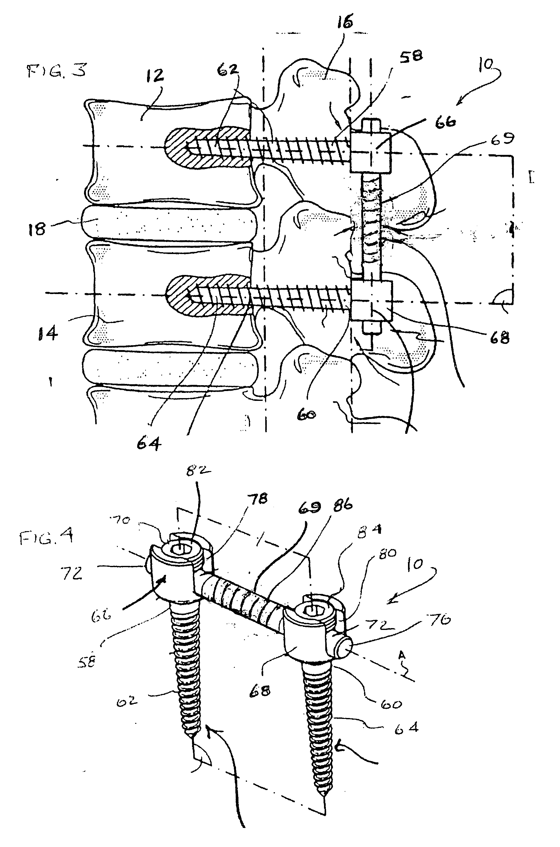
[0016] In attaching the flexible shaft to the external head ends of the anchoring members, the flexible shaft can be pre-bent to a desired bend orientation. The flexible shaft can be pre-bent to achieve varying degrees of lordosis (backward curvature) or kyphosis (forward curvature) prior to being affixed to the anchoring members and also the curvature of the flexible member depends upon the location along the spinal column, i.e. the cervical region would have a kyphotic curve while the lumbar region would have a lordotic curve. Thus, once installed to the vertebrae, the flexible shaft will provide the proper, desired curvature for the spinal column.
[0017] The actual placement of the flexible shaft in making up the dynamic stabilization system may also be by differing means. For example, the procedure can be minimally invasive such as by installing the flexible shaft by means of a guide wire through one or more small incisions in the patient. That guide wire itself can be shaped into the preferred curvature, that is, the flexible shaft can be slid over a lordotic configured guide wire as the flexible shaft passes over the guide wire. Alternatively, if the present dynamic stabilization system is installed during major surgery to install, for example, a replacement disc, the patient is already fully accessible for installation of the dynamic stabilization system.

Problems solved by technology

Unfortunately, the use of the fusion technique reduces the flexibility of the spinal column and results in some loss of activity of the patient.

Method used


Image

  • Dynamic spinal stabilization system
  • Dynamic spinal stabilization system
  • Dynamic spinal stabilization system

Examples


Embodiment Construction

[0030] Referring now to FIG. 1, there is shown a partially exploded view illustrating an exemplary dynamic spinal stabilization system 10 of the present invention affixed to the adjacent vertebrae 12, 14 of spinal column 16. As can be seen, the vertebrae 12, 14 are separated by a disc 18 that may be a natural disc or may be a prosthetic device that has taken the place of a normal disc by a replacement thereof. As shown, the upper portion of the vertebrae 12, 14 is the posterior side facing the posterior of the patient and the lower portion is the anterior side facing inwardly of the patient. Therefore it can be seen that the stabilization system is affixed proximate to the posterior of the spinal column 16.

[0031] There are a plurality of anchoring members 20, 22, 24 and 26 and are components of the present stabilization system 10 and two of the anchoring members, 20 and 24 are positioned side by side affixed to vertebra 12 and anchoring members 22, 26 are positioned side to side af...


PUM


Abstract

A spinal stabilization system for installation to the posterior of the spinal column that includes a pair of anchoring members affixed to adjacent vertebrae and which may have screw threads to carry out that affixation. The anchoring members each have external head ends for the attachment of a flexible shaft that thus spans between the vertebrae and allows motion between those adjacent vertebrae. The flexible shaft is made of a monolithic body having no moving components that could generate debris and fail mechanically. Exemplary flexible shafts suitable for use in this system includes one having at least one slot that may be a spiral slot, a shaft having pairs of oppositely disposed slots formed in the body with adjacent pairs angularly displaced apart or a flexible shaft having a serpentine slot formed therein. The flexible shaft is controlled to have a desired flexibility.

Description

FIELD OF THE INVENTION [0001] The present invention relates to a system for interconnecting vertebrae of a spinal column of a patient, and, more particularly, to a system that is affixed to the vertebrae and which has a predetermined dynamic flexibility to allow motion between the vertebrae while providing support for the spinal column. BACKGROUND OF THE INVENTION [0002] In the field of spinal devices and techniques, there is a common practice today of fusing adjacent vertebrae together in order to compensate for a damaged disc located intermediate those vertebrae. Unfortunately, the use of the fusion technique reduces the flexibility of the spinal column and results in some loss of activity of the patient. With the fusion procedure, there may be emplaced both an anterior spacer and rigid posterior element that “lock” the adjacent vertebrae together with the appropriate spacing, thus eliminating pain and restoring the correct anatomical position. [0003] With the advent, however of m...

Claims


Application Information

Patent Timeline
Patent Type & Authority Applications(United States)
IPC IPC(8): A61F2/30
CPCA61B17/7007A61B17/701A61B17/7032A61B17/7028A61B17/7026
Inventor MARTINEZ, JAIMEDINELLO, ALEXANDRE M.
Owner MEDICAL DEVICE CONCEPTS
Why Eureka
Try Eureka