Prostheses for Spine Facets

a technology of prosthesis and spine, applied in the direction of prosthesis, spinal implants, coatings, etc., can solve the problems of facet hypertrophy and spinal canal and foraminal compromise, increased stress on adjacent motion segments, and often successful approaches

Inactive Publication Date: 2007-01-18
UNIV OF SOUTH FLORIDA
View PDF5 Cites 69 Cited by
  • Summary
  • Abstract
  • Description
  • Claims
  • Application Information

AI Technical Summary

Benefits of technology

[0013] The device of the present invention allows for the repair of diseased or damaged posterior spine elements in the spine, including, but not limited to the lumbar region. The device returns the mechanical function of the facets to normal. T

Problems solved by technology

Ultimately, this leads to facet hypertrophy and spinal canal and foraminal compromise.
This approach, while often successful, is not ideal.
Fusing one segment leads to increased stresses on adjacent motion segments, which will accelerate the degenerative process in those locations.
The long-term effects of indwelling metallic instrumentation, while poorly documented, include stress-shielding, infection, a risk of hardware fatigue, breakage, migration, particulate debris which can cause inflammation, and radiographic artifacts.
In this population, successful disc replacement does not completely address the disease process, as the degenerated joints are still a problem as long as they are still subject to motion, and as long as spinal stenosis, instability, etc. remain.
Fusing the vertebra puts additional stress on the adjacent discs, which can result in early failure, and limits patient flexibility.
Such permanent screws can migrate causing serious complications.
The surface areas, so treated, are small a

Method used


Image

  • Prostheses for Spine Facets
  • Prostheses for Spine Facets
  • Prostheses for Spine Facets

Examples


Embodiment Construction

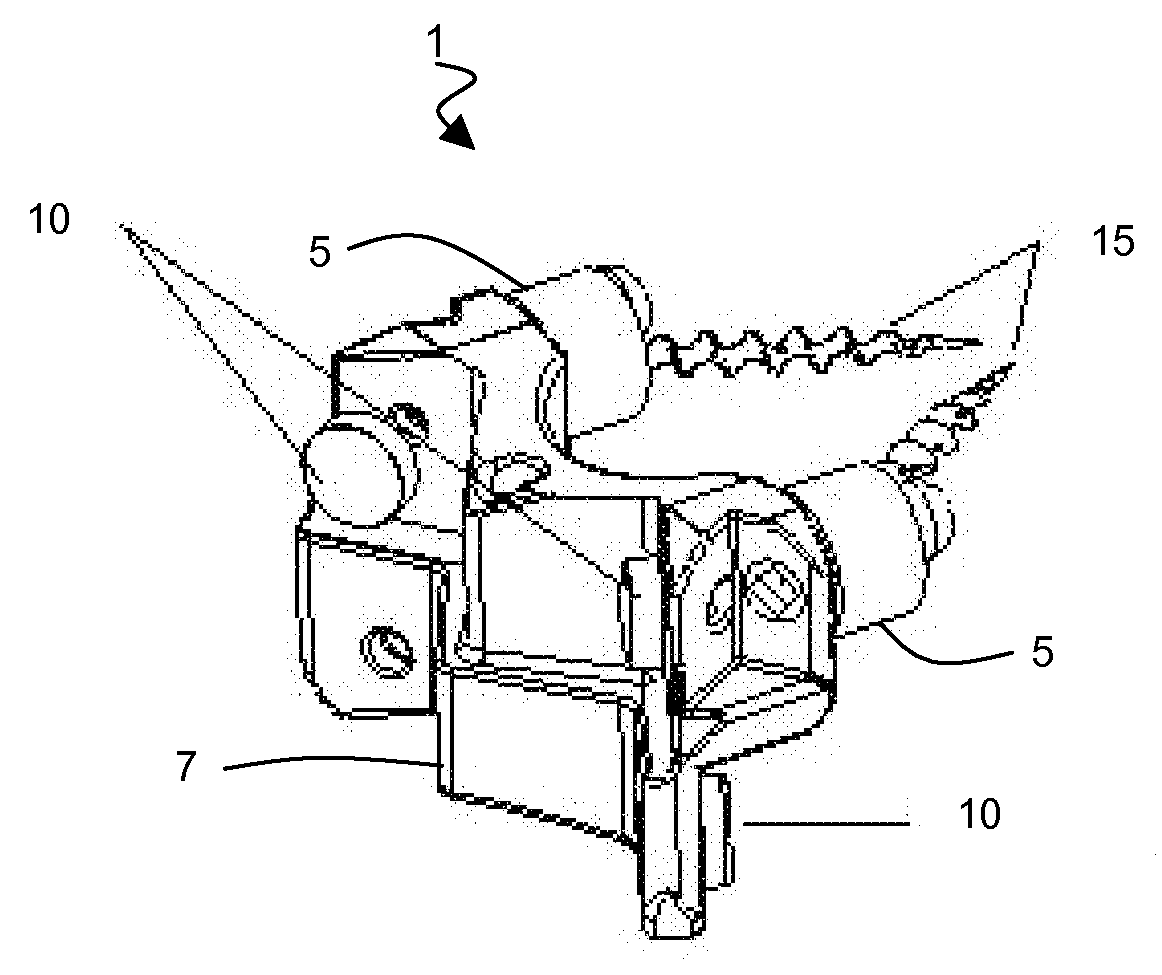
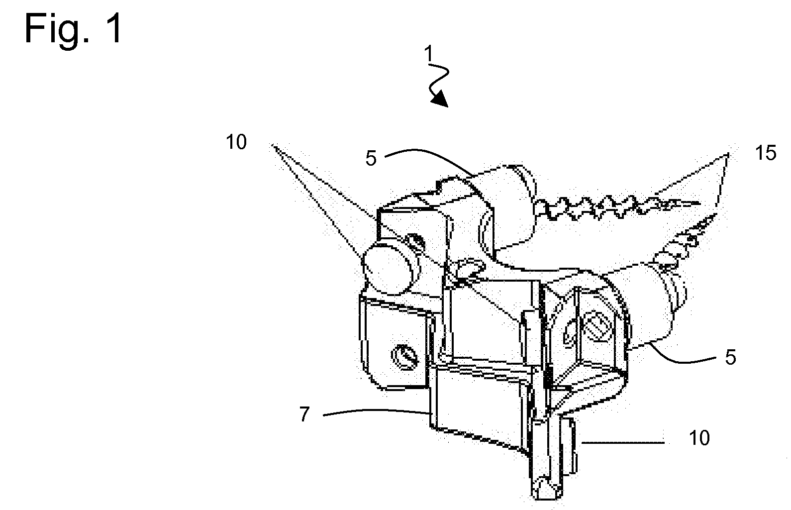
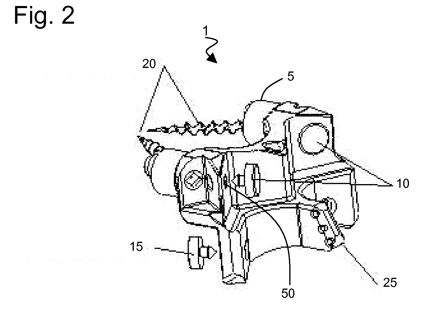
[0041] With reference to FIG. 1 through FIG. 12, the present invention comprises a combination of various sizes of three components configured into a prosthesis 1 for the replacement of a spinal facet. The first part is a monolithic block referred to as a posterior arch structure 7. The second part is a bearing element called the facet bearing button 10, 15. The third part is the attachment screw set 20. In a particular embodiment, these parts are arranged in a surgical kit which allows the surgeon a range of different combinations of posterior arch structure components, bearing buttons, and screw lengths to fit a wide range of individual patients.

[0042] In accordance with the present invention, two different median posterior arch structure (PAS) block sizes are provided. One for L1, L2, and L3 (designated PAS123) and one for L4 and L5 (designated PAS45). In both cases the PAS block is constructed of a similar material utilizing a similar processes. The major difference between PAS...


PUM

PropertyMeasurementUnit
Angleaaaaaaaaaa
Angleaaaaaaaaaa
Angleaaaaaaaaaa

Abstract

In accordance with the present invention is provided a prosthesis for the replacement of at least a portion of the bone of a facet located on a host mammalian vertebra. The prosthesis including a posterior arch structure having a plurality of bearing attachment surfaces, a plurality of facet bearing buttons releasably engaged with the bearing attachment surfaces, and a plurality of bioresorbable attachment screws to secure the posterior arch structure to the posterior vertebral articular process of the mammalian vertebra.

Description

CROSS REFERENCE TO RELATED APPLICATION [0001] This application is a Continuation of International Application No. PCT / US04 / 38753 filed on Nov. 18, 2004 which, claims priority to U.S. Provisional Patent Application No. 60 / 520,963 filed by the same inventor on Nov. 18, 2003, entitled: “Prostheses for Lumbar Spine Facets”.BACKGROUND OF THE INVENTION [0002] The end result of lumbar degenerative spondylosis comes from a combination of normal aging, disc dehydration, annulus disruption, and inflammation. The discs become desiccated, leaving the lumbar facets to carry more weight than for which they are suited. Ultimately, this leads to facet hypertrophy and spinal canal and foraminal compromise. The current operative treatment of lumbar spondylosis involves some combination of posterior decompression by laminotomy or laminectomy, with or without facetectomy, removal of the degenerated disc, with or without fusion via an anterior technique, posterior technique, or both. [0003] This approac...

Claims


Application Information

Patent Timeline
IPC IPC(8): A61F2/44
CPCA61F2/4405A61F2/442A61F2002/30299A61F2002/30616A61F2/30965A61F2310/00179A61F2310/00329A61F2310/00796A61F2310/00976A61F2230/0093
Inventor JOHNSON, WESLEY M.
Owner UNIV OF SOUTH FLORIDA
Why Eureka
Try Eureka