Determining and Tracking Downhole Particulate Deposition

a technology of particulate deposition and measurement, applied in the field of downhole tools, can solve the problems of clogging the production flow path, damage to expensive completion equipment, erosion of the wellbore, etc., and achieve the effect of convenient “tracking”

Inactive Publication Date: 2007-01-25
SCHLUMBERGER TECH CORP
View PDF13 Cites 16 Cited by
  • Summary
  • Abstract
  • Description
  • Claims
  • Application Information

AI Technical Summary

Benefits of technology

[0018] The methods and apparatus of the present invention may be practiced over a wide range of particulate material deposition operations. For example, the particulate material operations may include gravel packing, fracturing and proppant deposition as well as other operations performed in production wells. Likewise, the particulate material may be selected from gravel, proppants or combinations thereof. The proppant material may comprise manmade materials, natural materials or combinations thereof. In those applications of the present invention that include deposition of gravel, as in gravel packing operations, particular embodiments of the present invention include the deposition of the gravel to form a gravel pack within the isolated wellbore annulus. Optionally, particular embodiments include creating one or more fractures in the isolated wellbore annulus prior to or while carrying out the step of injecting the slurry and the particulate material into the one or more fractures.
[0019] The methods and apparatus of the present invention may be used within a portion of the wellbore annulus that is open-hole, cased or other form as known to those having ordinary skill in the art. For example, a portion of the wellbore defining the isolated wellbore annulus may include casing cemented therein with perforations formed through the casing and cement. Likewise, particular embodiments of the present invention are useful regardless of whether the portion of the wellbore defining the isolated wellbore annulus is horizontal.
[0020] In particular embodiments of the present invention, the composite density readings are acquired from one or more nuclear densimeters disposed within the tubular member and preferably, the one or more nuclear densimeters are distributed at discrete locations.
[0021] Further embodiments of methods according to the present invention are useful for characterizing fluid flow within a wellbore. Such methods comprise the steps of isolating a wellbore annulus defined by a tubular member disposed in the wellbore, injecting a fluid into the isolated wellbore annulus, acquiring composite density readings at one or more discrete locations along the tubular member during the step of injecting the fluid, and interpreting the acquired composite density readings to characterize the flow of the injected fluid within the isolated wellbore annulus. The injected fluid may be a slurry comprising a particulate material and a carrier fluid. The injected fluid may comprise an identifiable component, e.g., that makes the fluid easier to “track” by observation of a characteristic or “signature” density. The acquired composite density readings may be interpreted to determine the flow rate of the fluid within the wellbore.
[0022] Particular embodiments of the present invention include an apparatus for depositing particulate material within a wellbore that includes a plurality of densimeters secured at discrete axial locations within a tubular member for acquiring composite density readings within an isolated wellbore annulus during a particulate deposition operation. Preferably, the densimeters are nuclear densimeters. For use in some particulate material deposition operations, particular embodiments of the present invention include the tubular member as a wash pipe.
[0023] The foregoing and other objects, features and advantages of the invention will be apparent from the following more particular description of a particular embodiment of the invention, as illustrated in the accompanying drawing wherein like reference numbers represent like parts of the invention.

Problems solved by technology

In such formations, small particles (e.g., formation sand or fines) may be produced along with the desired formation fluids, which may cause several problems such as clogging the production flow path, erosion of the wellbore, and damage to expensive completion equipment.
Voids are created when the carrier fluid used to convey the gravel is lost or leaks off too quickly.
However, when the gravel slurry dehydrates too quickly, the gravel can settle out and form a “bridge” whereby it blocks the flow of slurry beyond that point, even though there may be void areas beneath or beyond it.
This can defeat the purpose of the gravel pack since the absence of gravel in the voids allows fines to be produced through those voids.

Method used


Image

  • Determining and Tracking Downhole Particulate Deposition
  • Determining and Tracking Downhole Particulate Deposition

Examples


Embodiment Construction

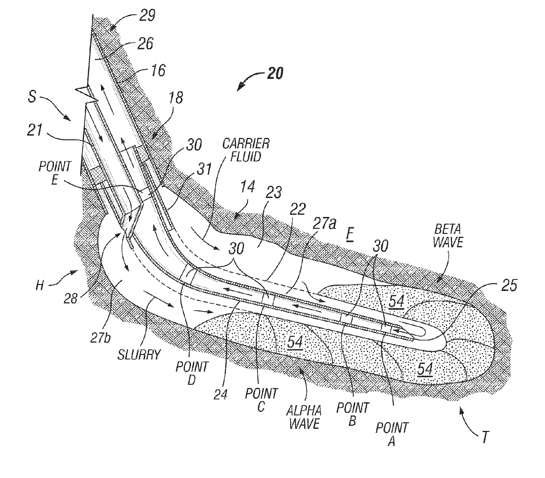
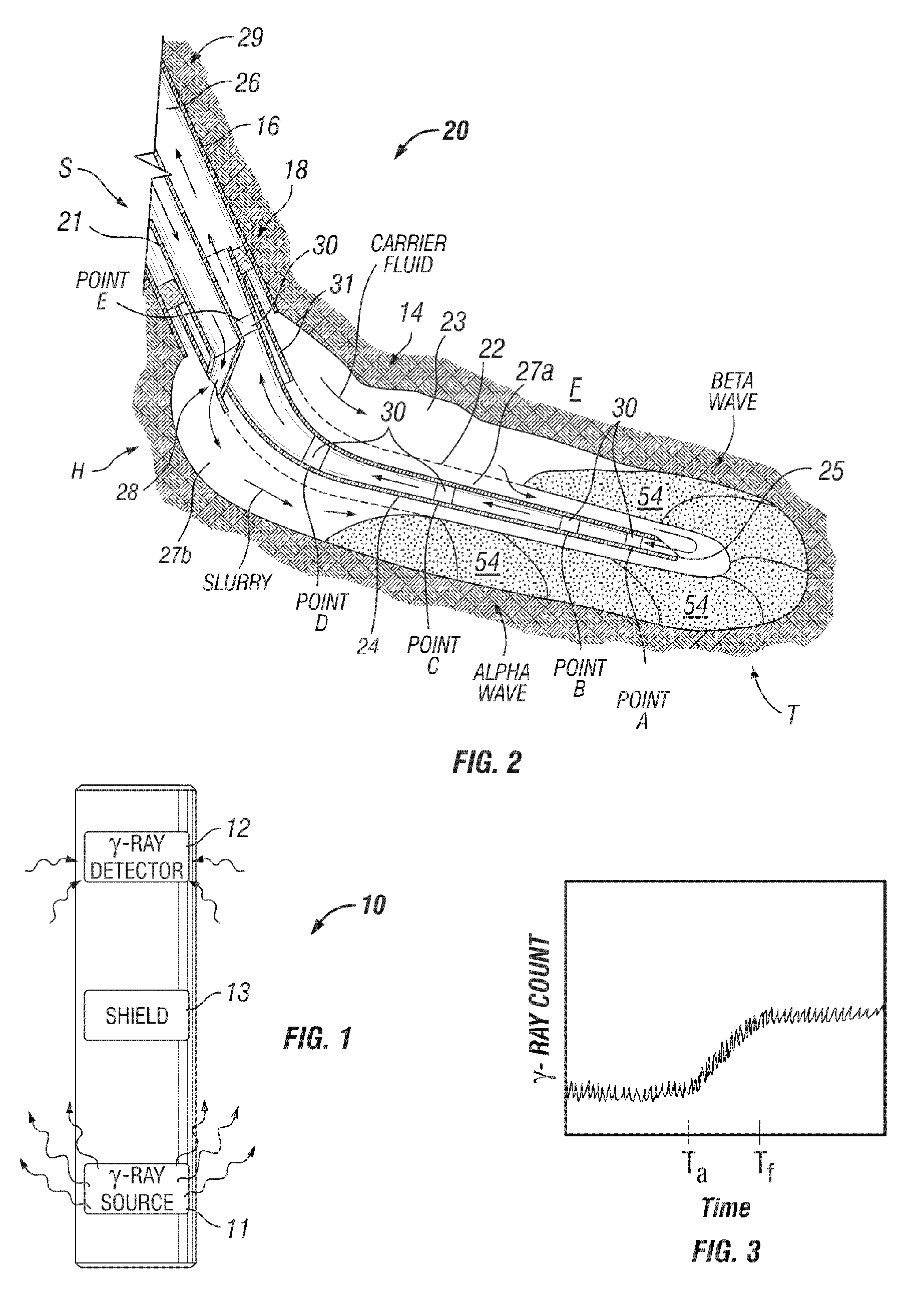
[0027] The present invention provides methods and apparatus that are useful for characterizing the injection of fluid(s) into a wellbore, such as during particulate packing operations like gravel packing and proppant deposition. While the field of particulate packing operations includes a wide variety of methods and apparatus, those having ordinary skill in the art will appreciate that the present invention may be implemented without limitation to a particular type of operation, method or equipment configuration. Therefore, while many of the embodiments of the present invention described herein include gravel packing operations, the present invention is not so limited.

[0028] Particular embodiments of the methods and apparatus of the present invention include the use of nuclear densimeters, which are well known to those having ordinary skill in the art. For example, the nuclear tools disclosed by Storm have been used for decades to determine the density of earth rock formations surr...


PUM


Abstract

Methods and apparatus provide for the characterization of injected fluid flow within a wellbore. Particular embodiments include injecting a slurry comprising a particulate material and a carrier fluid into an isolated wellbore annulus and acquiring composite density readings at one or more discrete locations along the annulus while depositing the particulate material. Interpreting the acquired composite density readings provides an evaluation of the placement of the deposited particulate material within the isolated wellbore annulus. A further step may include determining when the slurry reaches each of the discrete locations as indicated by increases in the composite density reading at each of the discrete locations and furthermore, acquiring a maximum composite density reading at each of the discrete locations along the tubular member as an indication of the quantity of deposited particulate material at each of the discrete locations. Apparatus includes a plurality of densimeters secured at discrete axial locations within a tubular member for acquiring composite density readings within an isolated wellbore annulus.

Description

BACKGROUND OF THE INVENTION [0001] This invention relates to downhole tools used in subsurface well completion and more particularly to tools used to enhance the effectiveness of particulate packing operations. [0002] Gravel packing is a method commonly used to complete a well in which the producing formations are loosely or poorly consolidated. In such formations, small particles (e.g., formation sand or fines) may be produced along with the desired formation fluids, which may cause several problems such as clogging the production flow path, erosion of the wellbore, and damage to expensive completion equipment. Production of particles such as fines can be reduced substantially using a steel wellbore screen in conjunction with particulate material sized to prevent passage of formation sand through the screen. Such particulate material, referred to as “gravel,” is pumped as a gravel slurry and deposited into an annular region between the wellbore and the screen. The gravel, if proper...

Claims


Application Information

Patent Timeline
Patent Type & Authority Applications(United States)
IPC IPC(8): E21B47/10E21B47/01E21B43/04E21B43/267
CPCE21B47/10E21B43/04G01V5/12
Inventor HURST, GARY D.LORDE, JULIETMONSEQUE, ALAN
Owner SCHLUMBERGER TECH CORP
Why Eureka
Try Eureka