Hydraulic steering arrangement

a steering arrangement and hydraulic technology, applied in the direction of steering parts, fluid steering, power driven steering, etc., can solve the problems of unpleasant driving experience and substantial production effort of the driver

Active Publication Date: 2007-01-25
DANFOSS PAUER SOLYUSHENS APS
View PDF24 Cites 3 Cited by
  • Summary
  • Abstract
  • Description
  • Claims
  • Application Information

AI Technical Summary

Benefits of technology

[0018] It is preferred that the steering unit and the control valve are connected to the control inlet of the directional valve via a change-over valve arrangement. Thus, the directional valve always reacts to the higher of the two pressures from control valve and steering unit. When the outlet pressure of the control valve is limited, it can thus be ensured in a simple manner that the steering via a steering handwheel and the steering unit always has priority over the steering with the control valve.
[0019] It is also advantageous that the control valve is connected to the control inlet of the flow control valve, the flow control valve being connected to the control valve via a feed-back unit. Thus, the flow control valve is no longer controlled through the directional valve. However, via the feed-back unit, for example a position sensor, which reacts to the slide of the flow control valve, it can always be ensured that the flow control valve permits the flow of hydraulic fluid to the steering motor connections in the desired manner.

Problems solved by technology

Often, the driver finds this unpleasant.
However, the required production efforts would be substantial.

Method used


Image

  • Hydraulic steering arrangement
  • Hydraulic steering arrangement
  • Hydraulic steering arrangement

Examples


Embodiment Construction

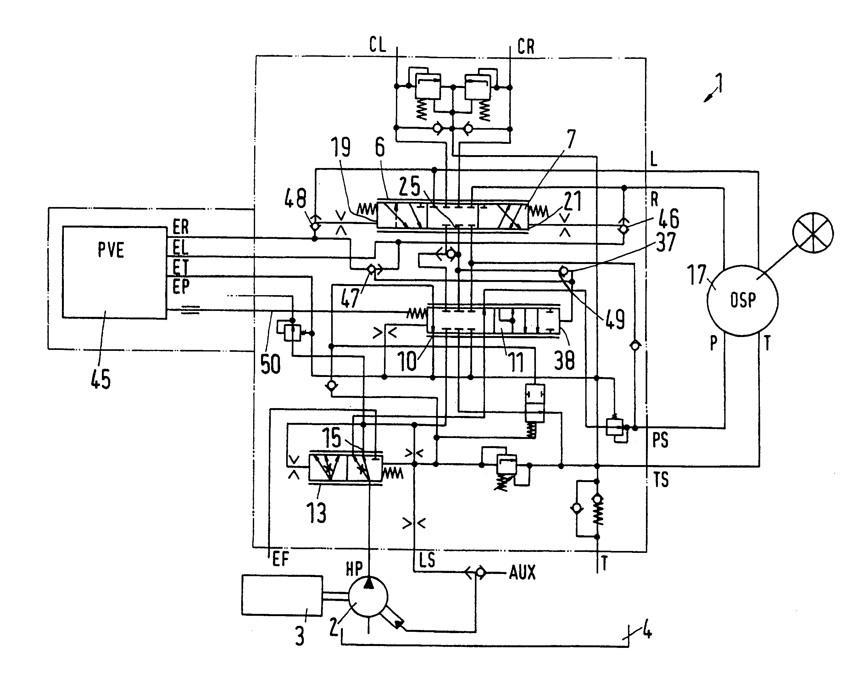
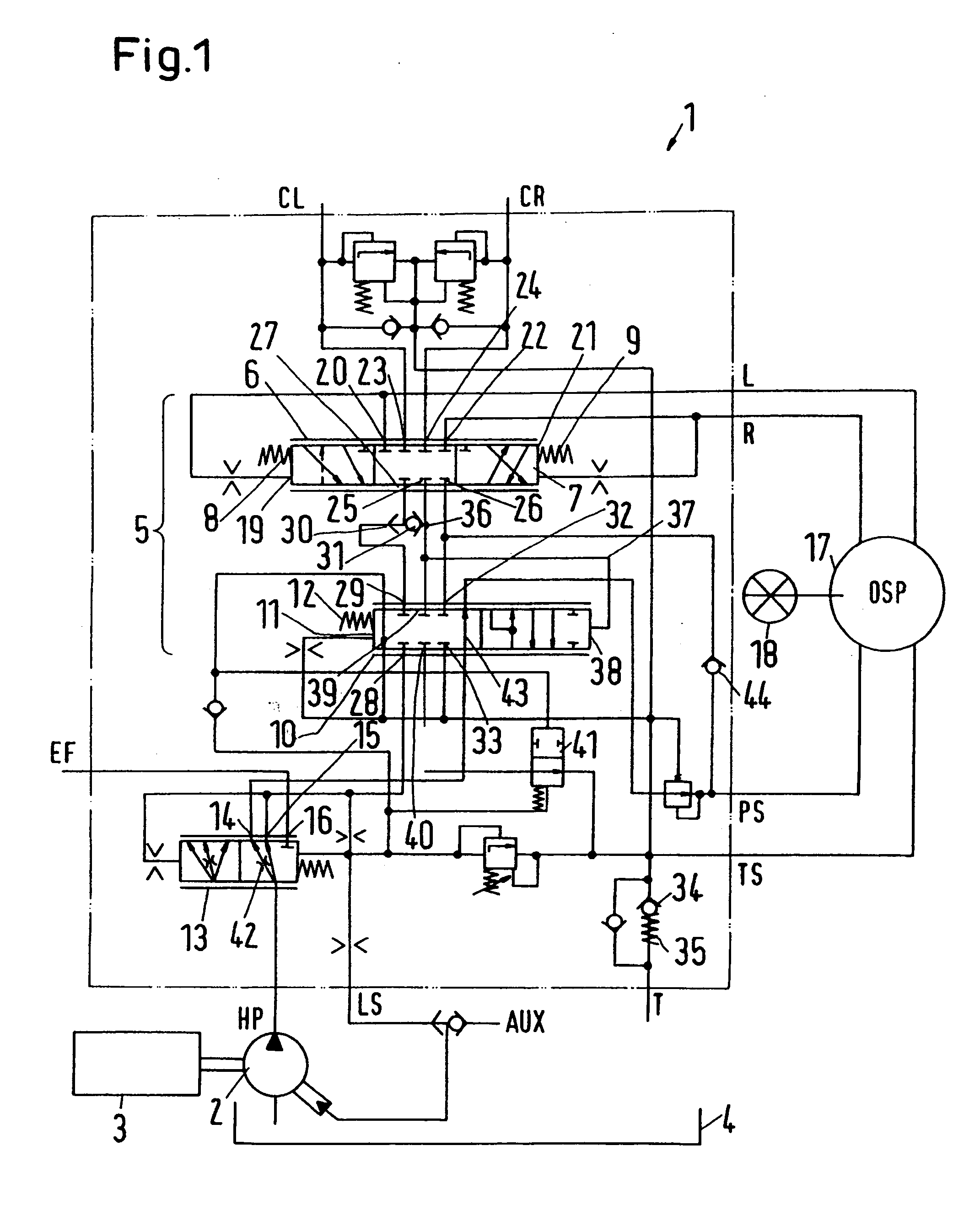
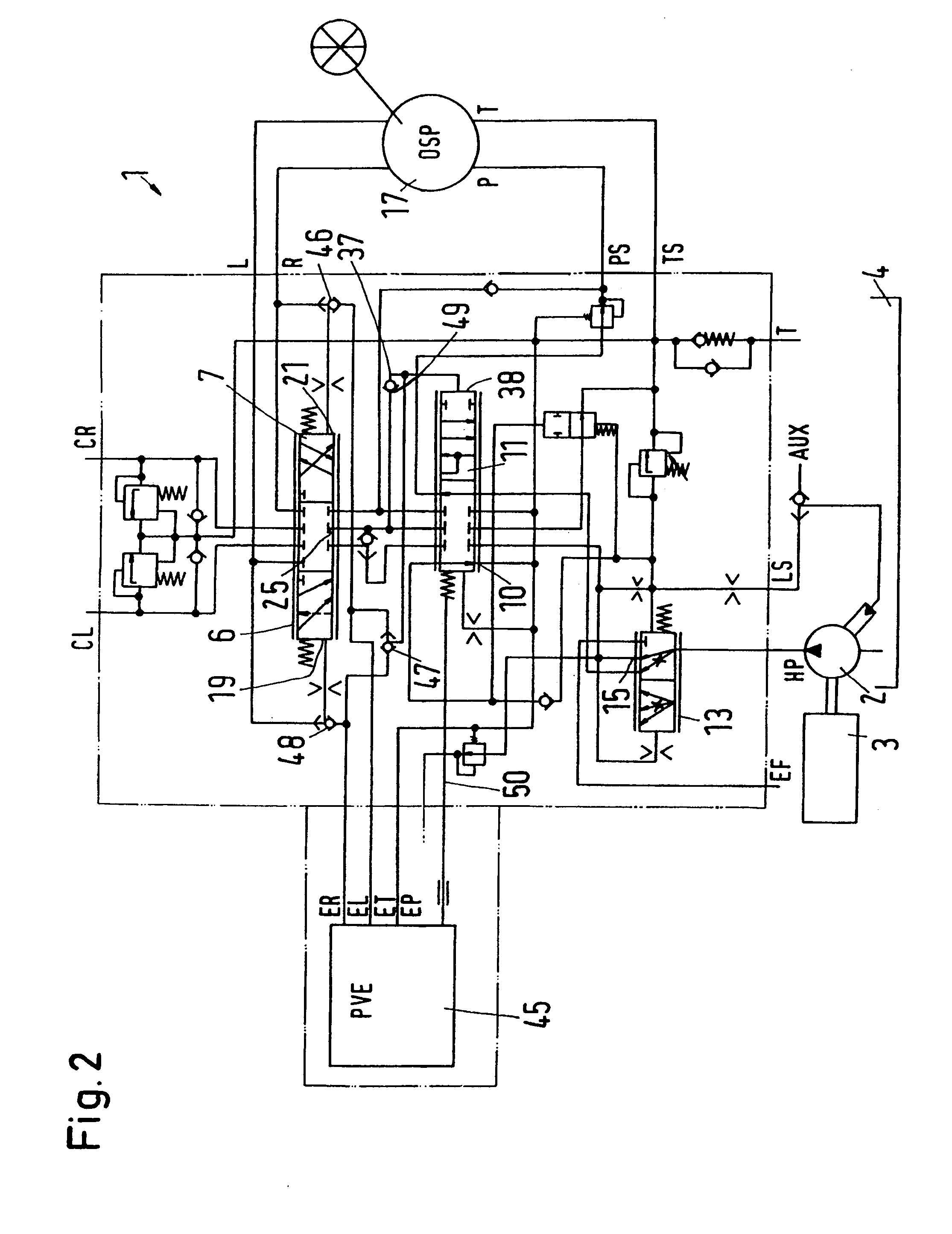
[0023]FIG. 1 shows a hydraulic steering arrangement 1 with steering motor connections CL, CR and supply connections HP, T. Additionally a load-sensing connection LS is provided at the supply connections HP, T.

[0024] A steering motor can be connected to the steering motor connections CL, CR, said motor being used for steering a vehicle, not shown in detail. A pump 2 is connected to a high-pressure connection HP, the pump 2 being driven by a motor 3, for example the drive motor of the vehicle. The other supply connection T ends in a tank 4.

[0025] The steering arrangement 1 has a steering valve arrangement 5, which both determines a deflection direction and a deflection speed of the steered members of the vehicle.

[0026] The steering valve arrangement has a directional valve 6 with a directional valve slide 7. In a neutral position, the directional valve slide is loaded by two springs 8, 9. The springs 8, 9 define an actuation pressure, which is, for example, in the range from 3 to 5...


PUM


Abstract

The invention concerns a hydraulic steering arrangement with a hydraulically actuated steering valve arrangement, steering motor connections (CL, CR), which are connected to supply connections (HP, T) via the steering valve arrangement, and a steering unit. It is endeavoured to equalize in a simple manner the steering behaviour in both directions. For this purpose, it is ensured that the steering valve arrangement has a directional valve and a flow control valve.

Description

CROSS-REFERENCE TO RELATED APPLICATIONS [0001] Applicant hereby claims foreign priority benefits under U.S.C. § 119 from German Patent Application No. 10 2005 033 576.4 filed on Jul. 19, 2005, the contents of which are incorporated by reference herein. FIELD OF THE INVENTION [0002] The invention concerns a hydraulic steering arrangement with a hydraulically actuated steering valve arrangement, steering motor connections, which are connected to supply connections via the steering valve arrangement, and a steering unit. BACKGROUND OF THE INVENTION [0003] Such steering arrangements are, for example, known from DE 10 2004 027 971 A1. When a driver of a vehicle provided with such a steering arrangement wishes to steer the vehicle, he activates the steering unit. In dependence of the actuation of the steering unit, hydraulic pressures are generated, which activate the steering valve arrangement, thus releasing a flow path from the supply connections to the steering motor. [0004] It has no...

Claims


Application Information

Patent Timeline
Patent Type & Authority Applications(United States)
IPC IPC(8): B62D5/08
CPCB62D5/09B62D5/06B62D5/062B62D5/093
Inventor SOERENSEN, OLE VINCENTZ
Owner DANFOSS PAUER SOLYUSHENS APS
Why Eureka
Try Eureka