Electronic device holder

Inactive Publication Date: 2007-01-25
ASKEY COMP
View PDF5 Cites 18 Cited by
  • Summary
  • Abstract
  • Description
  • Claims
  • Application Information

AI Technical Summary

Benefits of technology

[0006] The present invention has been accomplished under the circumstances in view. It is therefore the main object of the

Problems solved by technology

After installation, it is difficult and takes much time to remove

Method used


Image

  • Electronic device holder
  • Electronic device holder
  • Electronic device holder

Examples


Embodiment Construction

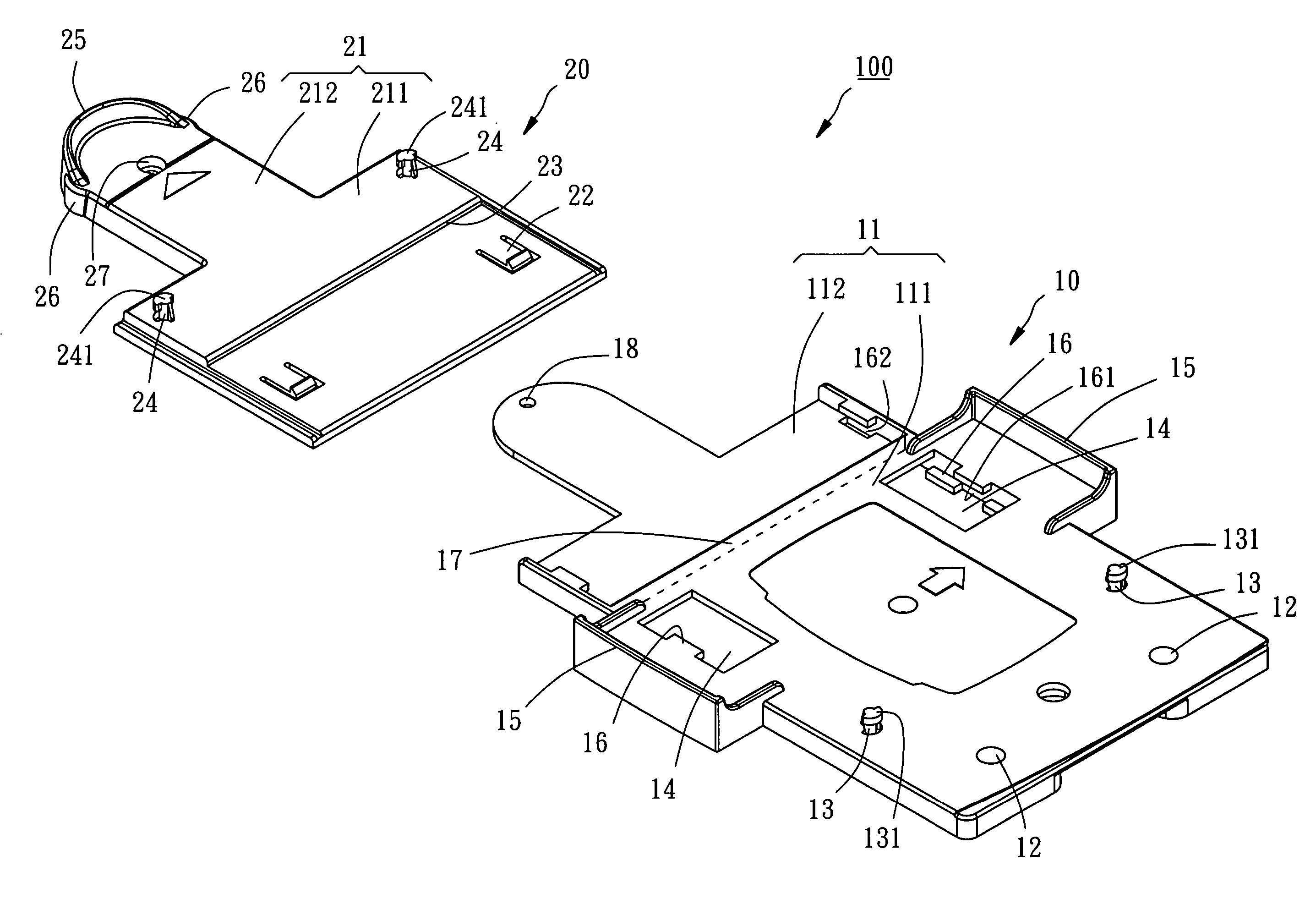
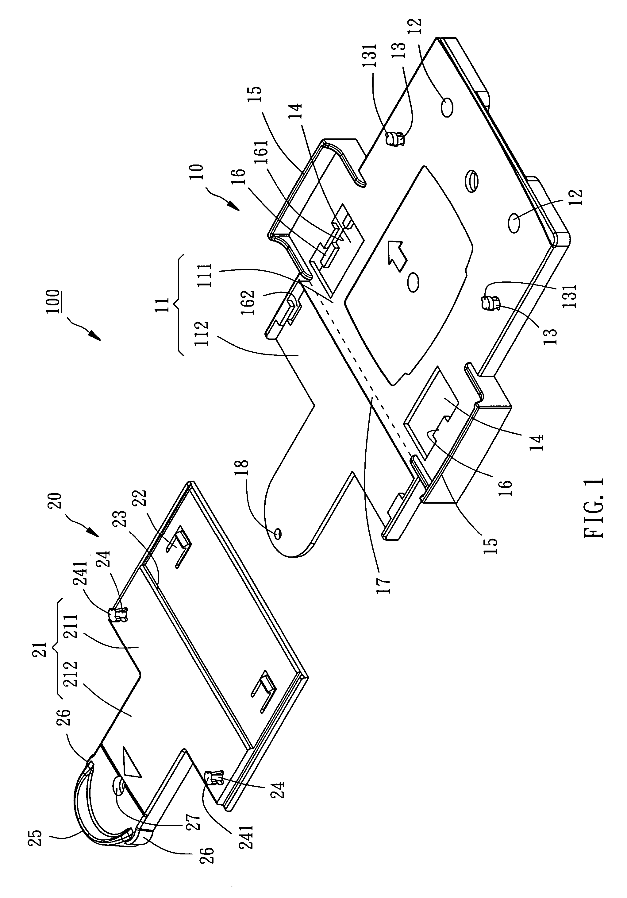
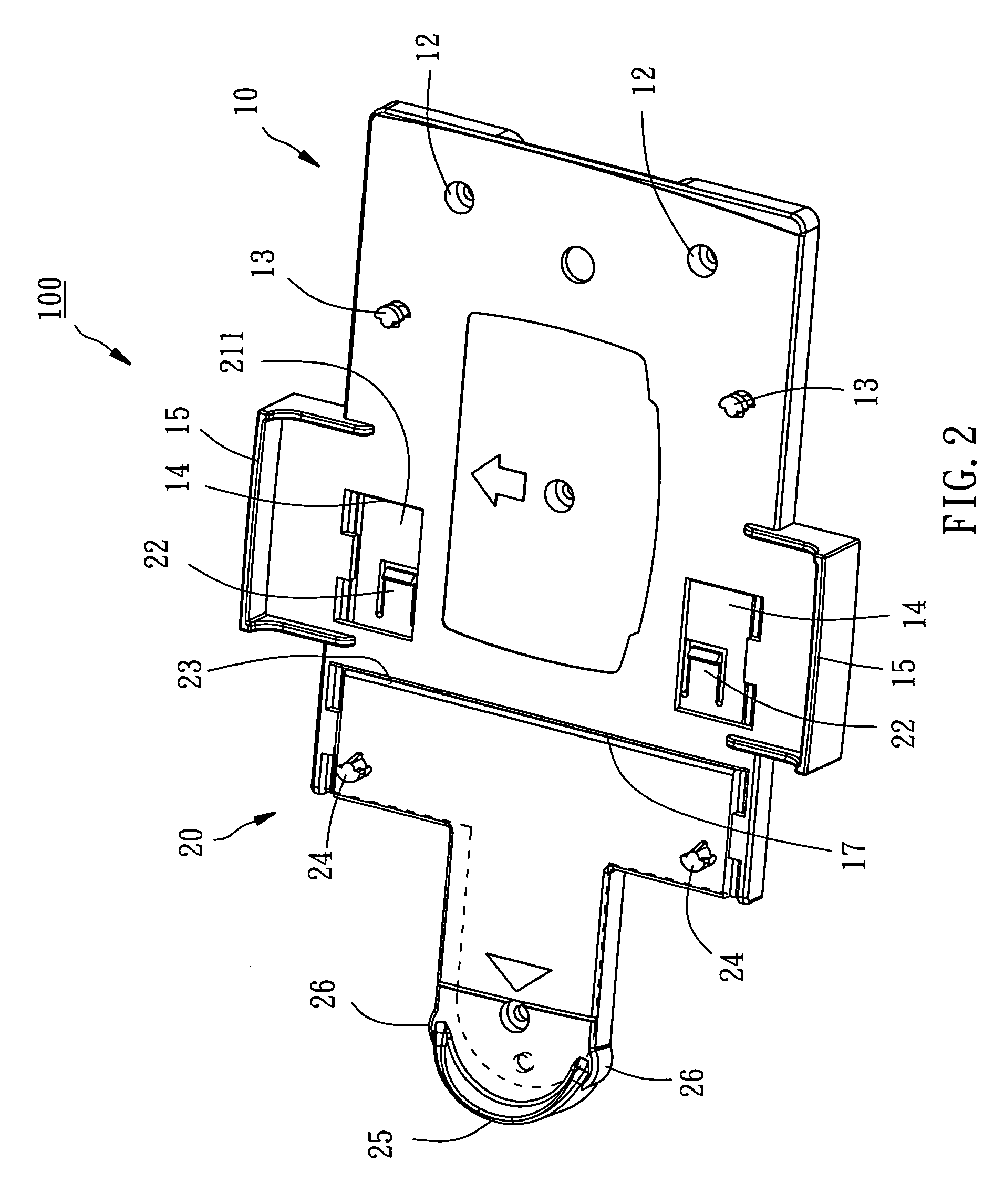
[0015] Referring to FIGS. 1-7, an electronic device holder 100 is shown comprised of a fixed bracket 10 and a movable bracket 20.

[0016] As shown in FIGS. 1, 2 and 7, the fixed bracket 10 comprises a flat base 11, a plurality of mounting holes 12, a plurality of locating rods 13, two openings 14, and two side flanges 15. The flat base 11 is a shaped plate member, having a top wall for accommodating an electronic device and a bottom wall opposite to the top wall. The bottom wall of the flat base 11 is to be adhered to a flat surface, for example the wall or ceiling. The top wall of the flat base 11 is divided into a first mounting zone 111 and a second mounting zone 112. The mounting holes 12 are provided at the first mounting zone 111 of the flat base 11 and cut through the top and bottom walls of the flat base 11. According to this embodiment, the number of the locating rods 13 is two. These two locating rods 13 extend upwards from the top wall of the flat base 11 in the first moun...


PUM


Abstract

An electronic device holder for holding thereon an electronic device includes a fixed bracket, which can be fixedly mounted on the wall or ceiling with screws or the like and has upright locating rods, and a movable bracket, which is coupled to the fixed bracket and has upright locating rods and is movable relative to the fixed bracket between a first position where the locating rods of the fixed bracket and the movable brackets are respectively disengaged from the electronic device put on the electronic device holder, and a second position where the locating rods of the fixed bracket and the movable bracket are respectively forced into engagement with the electronic device to lock the electronic device to the electronic device holder.

Description

BACKGROUND OF THE INVENTION [0001] 1. Field of the Invention [0002] The present invention relates to electronic device mounting techniques and more particularly, to an electronic device holder for holding an electronic device on the wall or ceiling. [0003] 2. Description of the Related Art [0004] An electronic device such as a wireless network receiver may be hung on and set inside the wall or ceiling to reduce room space occupation and to prevent obstruction of the sense of beauty of the room or house. [0005] Normally, screws or other fastening members are used to directly affix the electronic device on or inside the wall or ceiling. After installation, it is difficult and takes much time to remove the electronic device from the wall or ceiling for a repair work. SUMMARY OF THE INVENTION [0006] The present invention has been accomplished under the circumstances in view. It is therefore the main object of the present invention to provide an electronic device holder, which allows qui...

Claims


Application Information

Patent Timeline
IPC IPC(8): B65D19/00H05K5/02H05K7/12
CPCH05K5/0204
Inventor HUANG, WEN-LIANG
Owner ASKEY COMP
Why Eureka
Try Eureka