Movable type chain bucket ship unloader

A ship unloader, mobile technology, applied in the field of mobile chain bucket ship unloader, can solve the problems of large wear of the reclaiming head and screw blade, narrow application range, high energy consumption, etc., and achieve fast unloading speed and wide application range wide, low system energy consumption

Inactive Publication Date: 2016-08-03
JIANGSU WANBAO MACHINERY
View PDF10 Cites 6 Cited by
  • Summary
  • Abstract
  • Description
  • Claims
  • Application Information

AI Technical Summary

Problems solved by technology

The bridge type grab ship unloader with this structure is generally suitable for granular materials, the maximum output is only 1000 tons/hour, and the efficiency is poor;
[0004] 2. Through the form of transportation, the energy consumption is high; it is not suitable for powder materials;
The screw ship unloader with this structure has a large investment, and during the process of material retrieving and conveying, the reclaiming head and the screw blades are greatly worn, and the maintenance cost is high;
[0006] 4. Pneumatic ship unloader, such as CN205061019U discloses a high-throughput high-negative pressure pneumatic ship unloader, including suction nozzle, material delivery pipeline, intermediate storage silo, separator and its purging system, unloading lock a

Method used


Image

  • Movable type chain bucket ship unloader
  • Movable type chain bucket ship unloader
  • Movable type chain bucket ship unloader

Examples


Example Embodiment

[0045] Example 1:

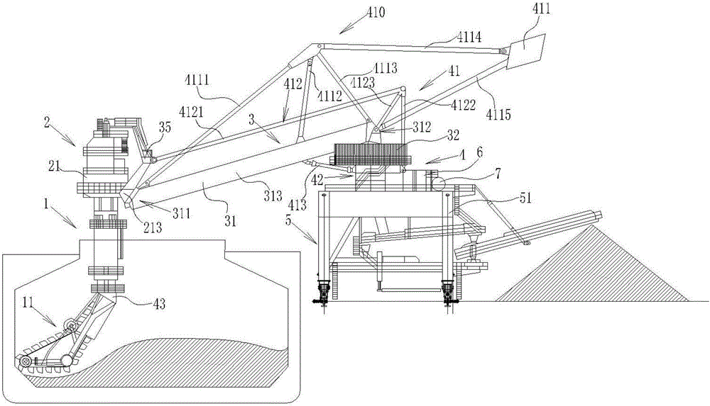
[0046] Cantilever pitching mechanism 41 adopts hydraulic system, such as figure 1As shown, the cantilever pitching mechanism 41 includes a balancing mechanism 410 , a stretching arm 412 and a push rod 413 . The balance mechanism 410 includes a balance piece 411, the balance piece 411 is connected and fixed by five balance beams, the balance piece 411 is located on the extension direction of the cantilever output end 312 of the cantilever delivery system 31; its five balance beams are respectively the first balance beam 4111, The second balance beam 4112, the third balance beam 4113, the fourth balance beam 4114 and the fifth balance beam 4115; wherein, the first balance beam 4111, the second balance beam 4112, the third balance beam 4113 and the fourth balance beam 4114 One end is connected to a point, which is located above the cantilever conveying system 31, the other end of the first balance beam 4111 is connected above the cantilever input end 311 of t...

Example Embodiment

[0047] Example 2:

[0048] The cantilever pitching mechanism 41 adopts a winch system, and its structure is basically the same as that of Embodiment 1, including a balancer 410 and a push rod 413. The structures of the balance mechanism 410 and the push rod 413 are the same as those in Embodiment 1, the difference is , also includes a hoisting mechanism, the hoisting mechanism includes a pull rope and a hoist, the pull rope is located at the position of the first stretch rod 4121 and the second stretch rod 4122 in Embodiment 1, and also includes a pole 4123, and the end of the pole 4123 is provided with One end of the pulley is connected to the connecting arm 35 of the reclaiming part, and is arranged along the length direction of the cantilever conveying system 31, bypasses the pulley, and is wound on the hoist. The hoist applies force to the connecting arm 35 of the reclaiming part and the cantilever conveying system 31 by retracting or releasing the pull rope, so that the c...


PUM


Abstract

The invention provides a mobile chain bucket ship unloader, which includes a retrieving mechanism, a conveying mechanism and a control mechanism. It is a chain-bucket reclaiming and lifting mechanism, and the conveying mechanism is a cantilever conveying mechanism. The chain-bucket reclaiming and elevating mechanism is connected with the cantilever conveying mechanism. A positioning mechanism is provided on the mechanism, and the positioning mechanism is controlled by a control mechanism. The positioning mechanism includes: a cantilever pitching mechanism and a cantilever turning mechanism. The invention provides a mobile chain-bucket ship unloader, which is a continuous type of retrieving and conveying, with fast unloading speed and wide application range; The unique swing mechanism can also take out the materials under the deck; the reclaiming section of the reclaiming system is equipped with a hydraulic tensioning device, which can reclaim the materials smoothly and completely remove the residual materials.

Description

technical field [0001] The invention relates to the technical field of ship unloaders, in particular to a mobile chain-bucket ship unloader with high material retrieving efficiency, low loss, strong adaptability and stable material retrieving. Background technique [0002] At present, there are several processes for bulk unloading: [0003] 1. Bridge type grab ship unloader, which takes materials through grab buckets. For example, CN103287984A discloses bridge type grab ship unloader, including steel structure system, operation system and unloading system. The unloading system includes a receiving plate system , a funnel and a feeding belt conveyor, the feed board system includes a sea side feed board, an intermediate feed board and a land side feed board, and the sea side feed board, the middle feed board and the land side feed board They are respectively installed on the sea-side column, funnel and land-side column. The feeding belt conveyor is a rotary belt conveyor. A ...

Claims


Application Information

Patent Timeline
IPC IPC(8): B65G67/60B65G65/04
CPCB65G67/60B65G65/04
Inventor 郭永平
Owner JIANGSU WANBAO MACHINERY
Why Eureka
Try Eureka