Textile discharging cart

A cart and bottom plate technology, applied in the field of textile processing, can solve the problems of troublesome unloading, time-consuming and labor-intensive, poor stability, etc., and achieve the effect of avoiding shaking, ensuring stability, and conveniently pushing the transport box

Inactive Publication Date: 2018-11-02
SUZHOU RUIZHONG NEW MATERIAL TECH CO LTD
View PDF0 Cites 11 Cited by
  • Summary
  • Abstract
  • Description
  • Claims
  • Application Information

AI Technical Summary

Problems solved by technology

[0003] The purpose of the present invention is to provide a textile unloading trolley, which has the advantage of being convenient for unloading, and solves the problems of poor stability, troublesome unloading, and time-consuming and labor-intensive problems.

Method used


Image

  • Textile discharging cart
  • Textile discharging cart
  • Textile discharging cart

Examples


Embodiment Construction

[0016] The following will clearly and completely describe the technical solutions in the embodiments of the present invention with reference to the accompanying drawings in the embodiments of the present invention. Obviously, the described embodiments are only some, not all, embodiments of the present invention. Based on the embodiments of the present invention, all other embodiments obtained by persons of ordinary skill in the art without making creative efforts belong to the protection scope of the present invention.

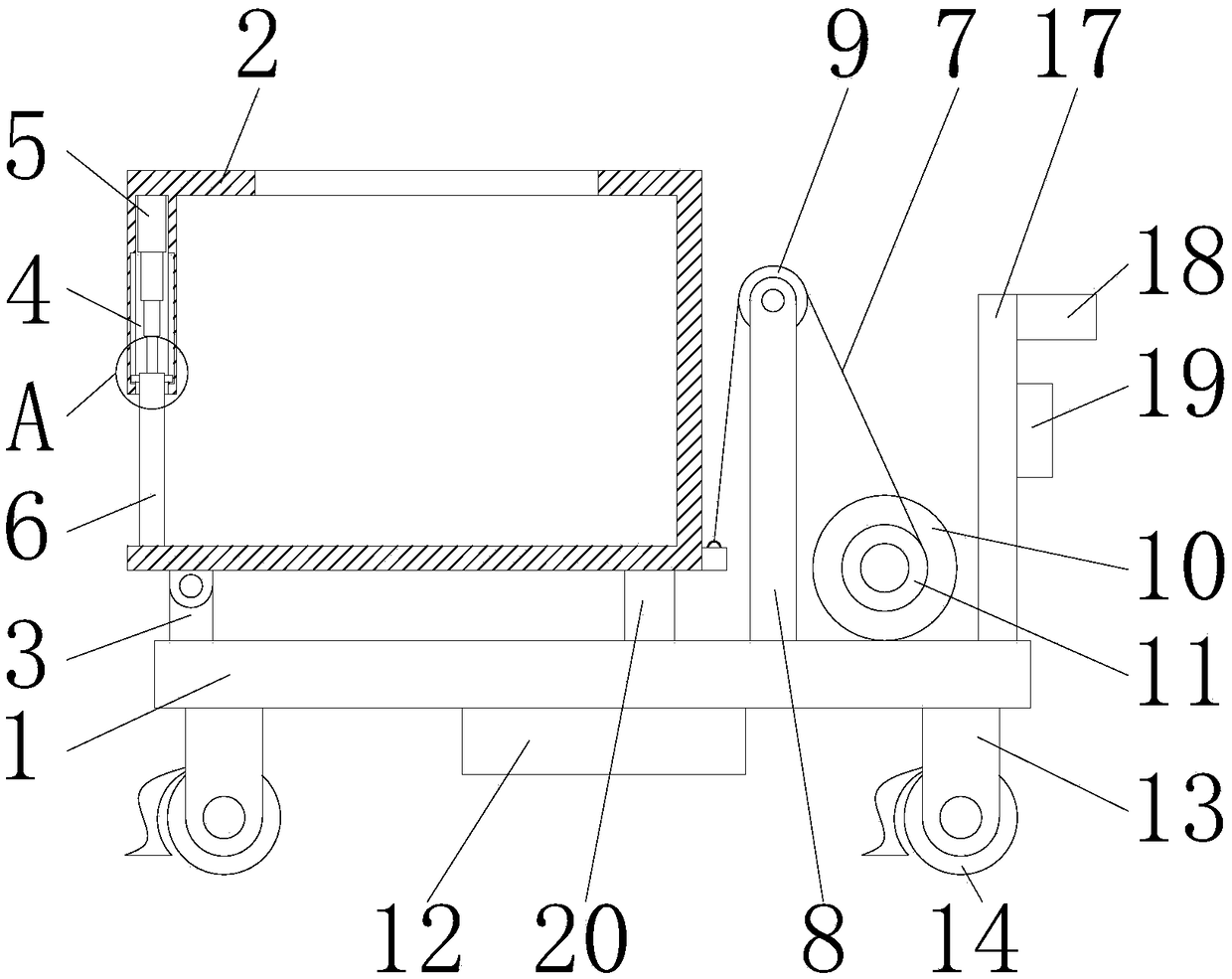
[0017] see Figure 1-3 , a textile unloading trolley, comprising a base plate 1 and a transport box 2, the left side of the top of the base plate 1 is fixedly connected with a fixed block 3, both sides of the bottom of the base plate 1 are fixedly connected with supporting legs 13, and the bottom of the supporting legs 13 The roller 14 is movably connected with the rotating shaft, and the bottom of the left side of the supporting leg 13 is movably connected wi...


PUM


Abstract

The invention discloses a textile discharging cart, comprising a bottom plate and a conveyer box. A fixing block is fixedly connected to the top left of the bottom plate; the top of the fixing block is movably connected with the conveyer box through a rotary shaft; the left surface of the conveyer box is provided with a movement channel; an electric telescopic rod is fixedly connected to the top of an inner cavity of the movement channel; a retaining plate is fixedly connected to the bottom of the electric telescopic rod; the bottom of the retaining plate is passed through the movement channeland is in contact with the bottom of the inner cavity of the conveyer box. The bottom plate, the conveyer box, the fixing block, the movement channel, the electric telescopic rod, the retaining plate, a rope, a support post, a pulley, a motor, a reel and a battery jointly form the textile discharging cart, wherein the motor drives the rope to telescope so that the conveyer box is inclined; the electric telescopic rod pulls the retaining plate to rise so that fabric in the conveyer box can be discharged quickly. The structural fit above enables the problems of poor stability, troublesome discharging and waste of time and manpower to be solved.

Description

technical field [0001] The invention relates to the technical field of textile processing, in particular to a textile unloading trolley. Background technique [0002] In the textile processing process, multi-step operations are generally required, so handling or transfer operations are required during the processing process. The fabric rolls or fabrics transported in the textile workshop are heavy, so a large amount of manpower is required to operate, so certain The efficiency of transportation has been reduced to a certain extent. Most of the textile carts in the prior art are composed of panels and rollers. Although they can realize the transfer of fabrics, their use stability is poor, and unloading is troublesome, time-consuming and laborious, and it is difficult to meet the needs of the market. need. Contents of the invention [0003] The object of the present invention is to provide a textile unloading trolley, which has the advantage of being convenient for unloadin...

Claims


Application Information

Patent Timeline
Patent Type & Authority Applications(China)
IPC IPC(8): B62B3/02B62B3/04B62B5/04B62B5/06
CPCB62B3/02B62B3/04B62B5/04B62B5/06
Inventor 文涛
Owner SUZHOU RUIZHONG NEW MATERIAL TECH CO LTD
Why Eureka
Try Eureka