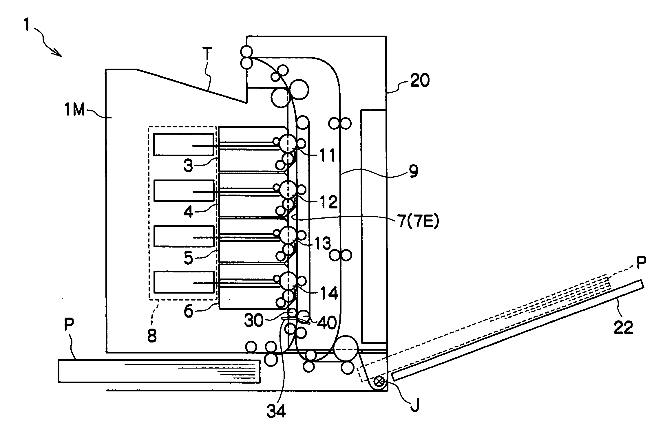
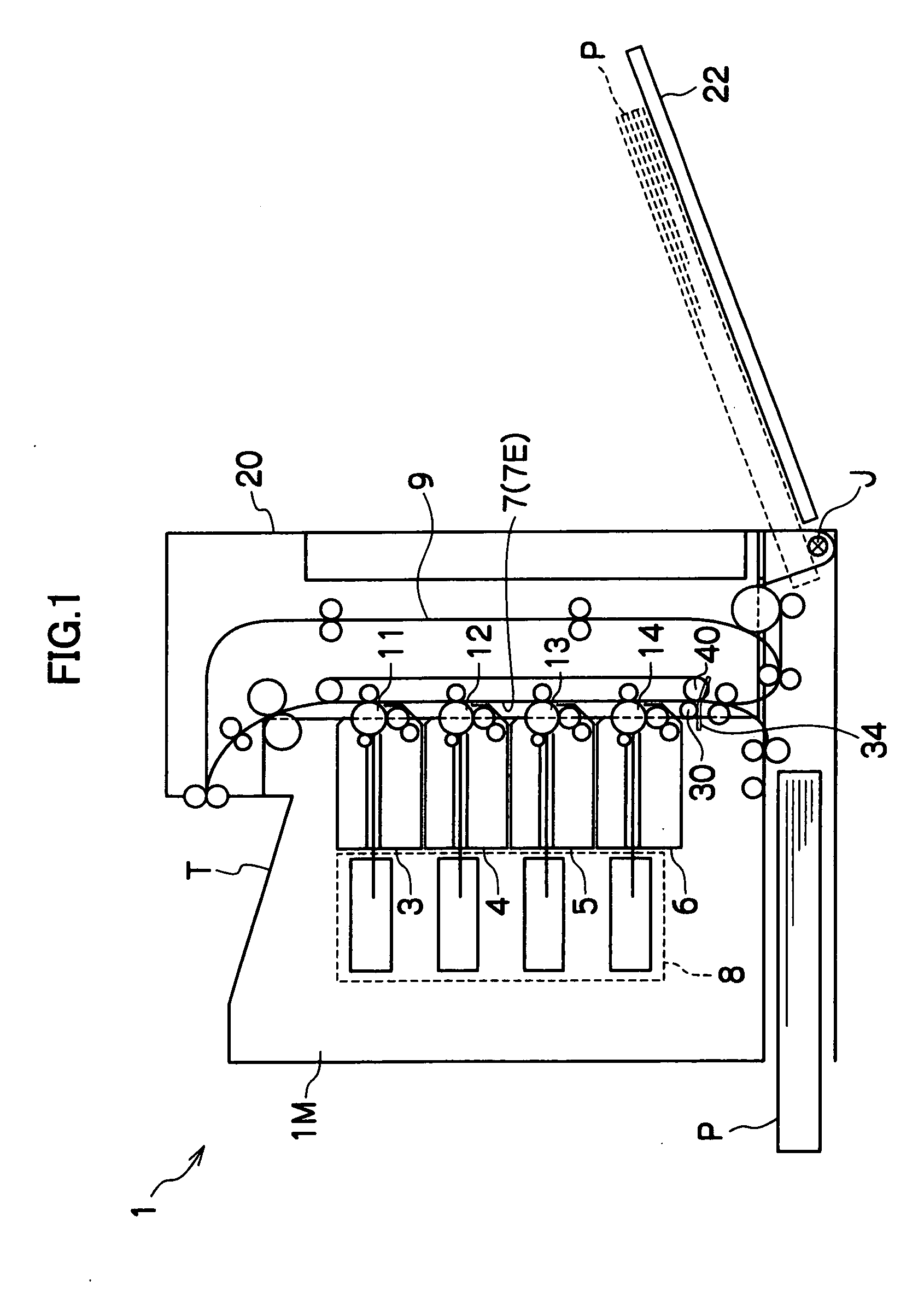
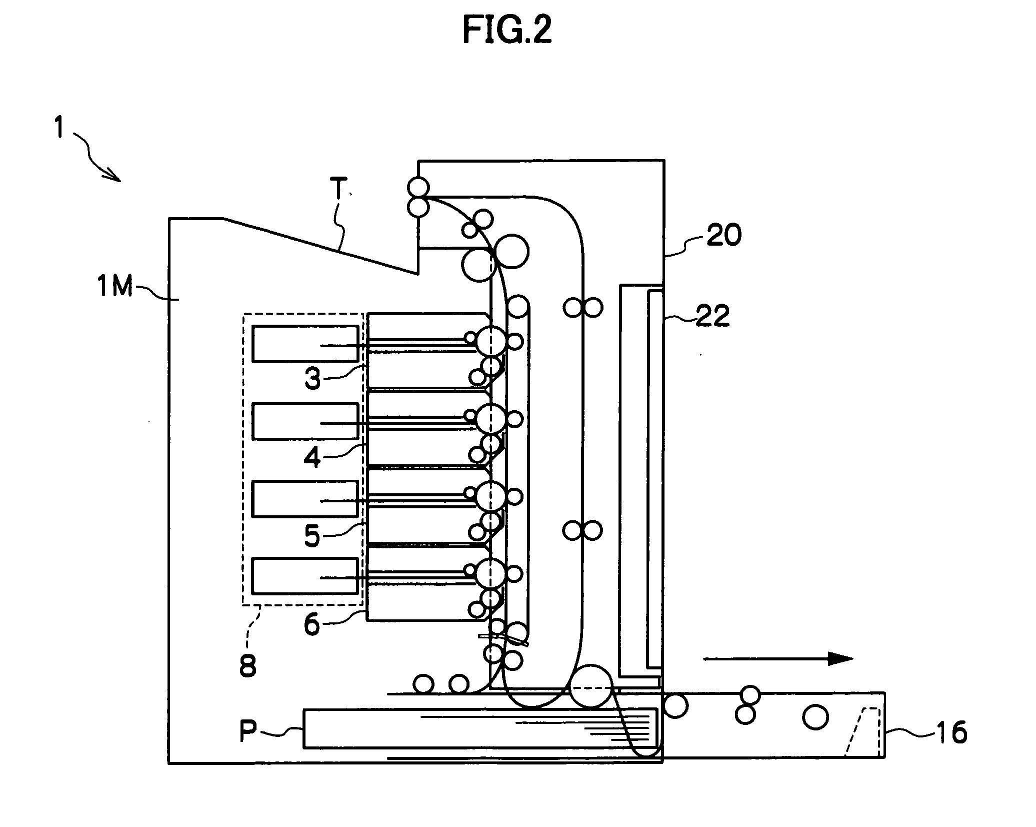
[0025] An embodiment of the present invention will be described hereinafter. As shown in FIGS. 1 and 2, a printer 1 relating to the embodiment of the present invention is a full-color printer. Note that the right side in FIG. 1 corresponds to the front side of the device, and the left side in FIG. 1 corresponds to the rear side of the device. Four process cartridges 3, 4, 5, 6 which are disposed in a vertical row substantially vertically, and a transfer belt 7 which is disposed along the process cartridges 3, 4, 5, 6, are provided within a printer main body 1M which structures the printer 1. The transfer belt 7 is opened, and the process cartridges 3, 4, 5, 6 can be installed and removed in a substantially horizontal direction into and from the open space. Photosensitive drums (image carriers) 11, 12, 13, 14 are provided at the process cartridges 3, 4, 5, 6, respectively.
[0026] The printer 1 has an ROS (Raster Output Scanner) 8 which carries out image exposure at the respective photosensitive drums 11, 12, 13, and 14. Electrostatic latent images formed on the photosensitive drums 11, 12, 13, 14 are respectively developed by toners of the colors of black (K), cyan (C), magenta (M), yellow (Y) at the process cartridges 3, 4, 5, 6. The ROS 8 which serves as an exposure device is structured from four semiconductor lasers which are driven and lit on the basis of image data corresponding to the respective colors of black (K), cyan (C), magenta (M), yellow (Y), and fθ lenses and polygon mirrors, and/or plural reflecting mirrors, for deflecting and scanning the four laser lights exiting from the four semiconductor lasers, and the like.
[0027] Beneath these process cartridges, the printer 1 has a sheet feed cassette 16 (see FIG. 2) which supplies sheets P which serve as transfer materials. A cassette accommodating section, which accommodates the sheet feed cassette 16 such that the sheet feed cassette 16 can be pulled-out therefrom, is formed at the printer main body 1M.
[0028] The printer 1 has a cover-like opening/closing portion 20, which structures the device side wall portion at the pull-out side (the front side in FIGS. 1 through 4) of the sheet feed cassette 16 above the sheet feed cassette 16. The opening/closing portion 20 is provided so as to be able to open and close the side surface of the device by being able to rotate around a rotation fulcrum J which is provided at the lower portion of the cassette accommodating portion. By opening the opening/closing portion 20, the process cartridges 3, 4, 5, 6 can be exposed and can be replaced, and maintenance with respect to paper jams or the like can be carried out in the state in which the photosensitive drums 11, 12, 13, 14 are exposed. The opening/closing portion 20 has a manual feed tray 22 which can open and close. A desired sheet P can be fed, from the exterior of the printer main body I M, through the manual feed tray 22.
[0029] In addition to the structures described above, the printer 1 also has a fixing device carrying out fixing processing on the sheet P to which toner images have been transferred; a conveying path 9 for double-sided printing, which conveys the sheet P, on whose one surface an image has been fixed by the fixing device, to the transfer section again in a state in which the obverse and reverse of the sheet P are reversed; a control circuit controlling operations of the printer; a controller structured from image processing circuits and the like, which carry out image processings on image signals; electrical circuits formed from a high-voltage power source circuit and the like; and the like. Note that, in FIGS. 1 through 4, T indicates a discharge tray into which the sheet P, on which an image has been formed, is discharged. This discharge tray T is disposed integrally with the top portion of the printer main body 1M.
(Opening/Closing Portion)
[0030] A structure that the rotational operation of the opening/closing portion 20 can be smooth, and that can position the opening/closing portion 20 when the opening/closing portion 20 is closed, will be described in detail hereinafter.
[0031] As shown in FIGS. 1 through 4, the opening/closing portion 20 is rotatably mounted to the printer main body 1M. By rotating and opening the opening/closing portion 20, the process cartridges 3, 4, 5, 6 accommodated in the printer main body 1M are exposed.
[0032] A belt outer peripheral surface 7E of a transfer belt 7 is positioned at the process cartridge side of the opening/closing portion 20 (toward the inside of the device main body) (see FIG. 5). (Here, the belt outer peripheral surface 7E refers to a portion of the outer peripheral surface of the belt 7, that faces the process cartridge side.) An attracting/holding roller 30 is provided at the opening/closing portion 20 so as to oppose the belt outer peripheral surface 7E. The roller surface of the attracting/holding roller 30 presses against the belt outer peripheral surface 7E.
[0033] A guide portion, which slidably guides the attracting/holding roller 30, is provided at the printer main body 1M. The attracting/holding roller 30 slides as the opening/closing portion 20 is opened and closed.
[0034] As shown in FIGS. 5 through 7, in the present embodiment, the attracting/holding roller 30 is provided as the opposing member. However, instead of the attracting/holding roller, a blade, a scraper, a brush, a secondary transfer roller, a cleaner, or the like may be provided.
[0035] The guide portion will be described hereinafter by using FIG. 8 through FIGS. 11A-11C. Guide rails (guide members) 34 which guide the attracting/holding roller 30 from the lower side, link members 36 which support the attracting/holding roller 30 at the both end portions, and tension coil springs 38 (see FIGS. 11A through 11C) which are mounted to the link members 36 and urge the attracting/holding roller 30 toward the belt outer peripheral surface 7E, are provided at the printer 1 as a guide portion 32. The guide rails 34 are provided at the printer main body 1M (see FIGS. 8 and 9).
[0036] As shown in FIGS. 11A through 11C, the tension coil springs 38 are hooked on projections (not shown) which are formed at the link members 36 and the opening/closing portion 20, and are disposed so as to urge the attracting/holding roller 30 toward a driving roller 40 which abuts the belt inner peripheral surface side of the transfer belt 7. When the opening/closing portion 20 is open and the attracting/holding roller 30 is not abutting the guide rails 34 (see FIG. 11A), the link members 36 is pulled by the tension coil springs 38, and further, movement thereof is restricted by stoppers (not shown), so that the attracting/holding roller 30 is positioned diagonally downward of the driving roller 40.
[0037] When the opening/closing portion 20 which is open is rotated in the closing direction, a rotating shaft projecting from the end portions of the attracting/holding roller 30 abuts the top surfaces of the guide rails 34 (see FIGS. 8, 9, and 10A). Note that in FIG. 8 through FIGS. 10A through C, for simplification, the drawings show the attracting/holding roller 30 abutting the guide rail 34, but in actuality, the rotating shaft of the attracting/holding roller 30 abuts the guide rails 34.
[0038] When the opening/closing portion 20 is rotated further in the closing direction, the attracting/holding roller 30 is guided by and slides on the top surfaces of the guide rails 34, such that the heightwise position of the attracting/holding roller 30 gradually rises (see FIG. 10B).
[0039] When the opening/closing portion 20 is completely closed, the attracting/holding roller 30 reaches a predetermined position (see FIG. 10C). The mounting positions of the tension coil springs 38 are determined such that, in this state, the tension coil springs 38 urge the link members 36 downward. In this way, there is a simple structure in which the guide rails 34 guide the attracting/holding roller 30 only from the lower side.
[0040] As described above, in the present embodiment, even if the attracting/holding roller 30 is disposed near to the cartridge6, the attracting/holding roller 30 and the cartridge 6 do not interfere with one another at times of opening and closing of the opening/closing portion 20, and therefore, the height of the device can be kept low. Further, because interference between the attracting/holding roller 30 and the cartridge 6 can be avoided regardless of the position of the rotating fulcrum J of the opening/closing portion 20, the degrees of freedom in selecting the position of the rotating fulcrum J increase.
[0041] The tension coil springs 38 are provided as described above. In this way, the urging forces which urge the attracting/holding roller 30 toward the driving roller 40 change in accordance with the open/closed state of the opening/closing portion 20. In the state in which the opening/closing portion 20 is open, the urging forces are released, and it is possible to make it such that sheets which have jammed are not nipped by the attracting/holding roller 30 and the driving roller 40. Therefore, the operability improves. In addition, the slid position of the attracting/holding roller 30 can be made to coincide with the open/closed position of the opening/closing portion 20, and problems in the sliding operation and the like can be prevented. Therefore, the reliability improves.
[0042] Further, because the link members 36 are provided as described above, the shaft-receiving portions of the attracting/holding roller 30, and the supporting members which support the attracting/holding roller 30 in order to slide the attracting/holding roller 30, can be structured integrally. In this way, the structure can be simplified, and costs can be reduced.
[0043] Because the attracting/holding roller 30 is provided at the opening/closing portion 20, maintenance, such as cleaning of the attracting/holding roller 30 and the like, is easy. Further, when the transfer belt 7 is replaced, the attracting/holding roller 30 can be replaced at the same time. Therefore, the workability at the time of replacing the attracting/holding roller 30 is good, and lifetime care of the attracting/holding roller 30 is easy. Moreover, it is easy to make the diameter of the attracting/holding roller 30 large, and the guidability at the time when a sheet is thrust-in improves. In addition, by opening the opening/closing portion 20, sheets which are nipped between the transfer belt 7 and the attracting/holding roller 30 can be easily removed, and the ability to clear paper jams is good.
[0044] The guide rails 34, which support the attracting/holding roller 30 while guiding the attracting/holding roller 30 at the times when the opening/closing portion 20 opens and closes, are provided at the printer main body 1M. In this way, when opening the opening/closing 20 portion, the locus of movement of the sliding of the attracting/holding roller 30 can be controlled reliably, and it is possible to reliably avoid interference between the attracting/holding roller 30 and the cartridge 6.
[0045] As described above, in accordance with the present invention, an image forming device in which the height of the device is kept low can be realized.
[0046] In the image forming device which is structured in this way, the opposing member is provided at the opening/closing portion, and not at the device main body. Therefore, the opening/closing portion can be positioned highly accurately.
[0047] Further, because the opposing member slides as the opening/closing portion is opened and closed, it is possible for the cartridges and the opposing member to not interfere with one another even if the opposing member is disposed near to the cartridges, and the height of the device can be kept low. Further, because interference between the opposing member and the cartridges can be avoided regardless of the position of the rotation fulcrum of the opening/closing portion, the degrees of freedom in selecting the position of the rotation fulcrum increase.
[0048] An embodiment of the present invention was described by using a full-color printer as an example. However, note that the above-described embodiment is an example, and the present invention can be implemented by making various changes within a scope which does not deviate from the gist thereof. Further, the scope of the present invention is, of course, not limited to the above-described embodiment.