Boundary acoustic wave device and process for producing same

a technology of acoustic waves and a process, applied in the direction of magnets, generators/motors, magnets, etc., can solve the problems of increasing the cost of surface acoustic waves, and affecting the frequency response of the device, so as to achieve a stable and effective production effect, and efficiently suppress the frequency variation

Active Publication Date: 2007-01-25
MURATA MFG CO LTD
View PDF6 Cites 35 Cited by
  • Summary
  • Abstract
  • Description
  • Claims
  • Application Information

AI Technical Summary

Benefits of technology

[0016] To overcome the problems described above, preferred embodiments of the present invention provide a method for stably and effectively producing a boundary acoustic wave device having target frequency characteristics, the method being able to efficiently suppress variations in frequency caused by production tolerance. Preferred embodiments of the present invention also provide a boundary acoustic wave device having target frequency characteristics with only slight non-uniformity in frequency from lot to lot.
[0032] When at least one medium has a laminated structure in which a plurality of material layers are laminated, the selection of the plurality of the material layers facilitate forming medium layers having different acoustic velocities therein or different frequency characteristics.

Problems solved by technology

The use of the package having the cavity inevitably increases the cost of the surface acoustic wave device.
Thus, the size of the surface acoustic wave device is relatively large.
However, according to experiments conducted by the inventors, production tolerance often induces non-uniformities in a resonant frequency and a center frequency in the boundary acoustic wave devices, as in the case of the surface acoustic wave devices.
However, since the oscillation energy of a boundary wave is scarcely distributed in a boundary acoustic wave device, such a method for adjusting the frequency cannot be used.
However, the frequency cannot be adjusted after completion.

Method used


Image

  • Boundary acoustic wave device and process for producing same
  • Boundary acoustic wave device and process for producing same
  • Boundary acoustic wave device and process for producing same

Examples


example 1

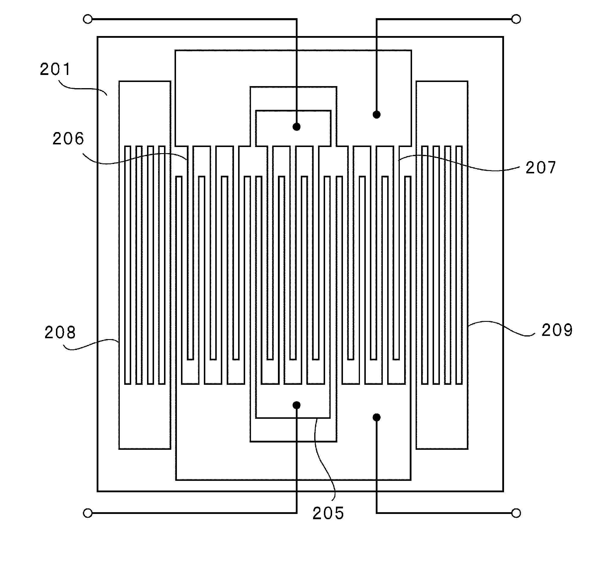
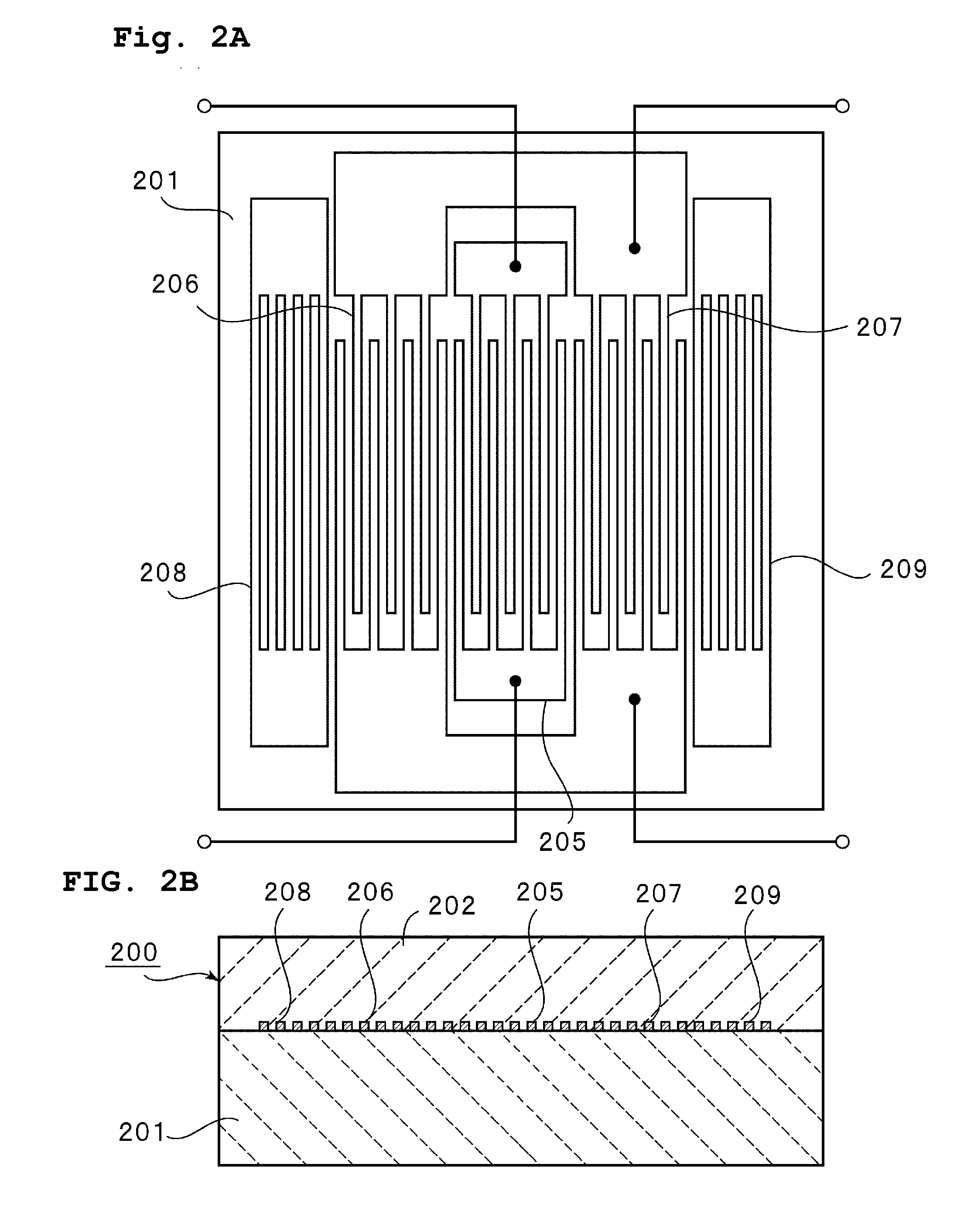
[0083] A 15° Y-cut X-propagating LiNbO3 substrate was prepared as a first medium. The electrode structure shown in FIG. 2 was formed on the LiNbO3 substrate. That is, the input IDT 205, the output IDTs 206 and 207, and the reflectors 208 and 209 shown in FIG. 2A were formed. The electrodes were made using the following procedure: after washing the LiNbO3 substrate, a resist was spin-coated thereon, prebaked, and developed to form a resist pattern. A NiCr film and then an Au film were formed in that order by vacuum evaporation. The resist was lifted-off. The resulting electrodes were washed. Thereby, the electrode structure including the Au film having a thickness of about 0.055λ and the NiCr film having a thickness of about 0.001λ was obtained.

[0084] Next, a SiO2 film as a second medium and having a thickness of about 0.1λ was formed over the surface having the electrodes of the LiNbO3 substrate by RF sputtering, thereby producing a laminate shown in FIG. 2B.

[0085] A resist was sp...

example 2

[0095] A 15° Y-cut X-propagating LiNbO3 substrate was prepared as a first medium. The electrode structure shown in FIG. 2A was formed as in EXAMPLE 1. Many LiNbO3 substrates each having the electrodes were prepared.

[0096] A SiO2 film was formed over the electrodes disposed on the LiNbO3 substrate by RF sputtering. In this case, structures having the SiO2 films with thicknesses of about 0.1λ, about 0.3λ, about 0.5λ, and about 1.0λ were produced. Then, a polycrystalline Si film having a thickness of about 0.5λ was formed on each SiO2 film by RF sputtering. Thereby, a laminate having a laminated structure of poly-Si / SiO2 / electrodes / LiNbO3 substrate, i.e., the laminate of third medium / second medium / electrodes / first medium was prepared.

[0097] At this point, a propagating boundary wave was not a boundary acoustic wave but a surface acoustic wave, in which displacement was concentrated on the surface. The frequency adjustment was performed for the surface acoustic wave.

[0098] A resist w...


PUM

PropertyMeasurementUnit
center-to-center distanceaaaaaaaaaa
mean center frequencyaaaaaaaaaa
frequencyaaaaaaaaaa

Abstract

In a method for producing a boundary acoustic wave device that includes a first medium, a second medium, and a third medium laminated in that order, and electrodes disposed at the interface between the first medium and the second medium, the method includes the steps of preparing a laminate including the first medium, the second medium, and the electrodes disposed at the interface between the first medium and the second medium, adjusting the thickness of the second medium after the step of preparing the laminate to regulate a frequency or the acoustic velocity of a surface acoustic wave, a pseudo-boundary acoustic wave, or a boundary acoustic wave, after the adjusting step, forming the third medium different from the second medium in terms of the acoustic velocity with which the boundary acoustic wave propagates therethrough and / or in terms of material.

Description

BACKGROUND OF THE INVENTION [0001] 1. Field of the Invention [0002] The present invention relates to a boundary acoustic wave device using a boundary acoustic wave propagating through the interface between media and a method for producing the boundary acoustic wave device. More specifically, the present invention relates to a boundary acoustic wave device including electrodes disposed between a first medium and a second medium, and another medium laminated on the outer surface of one of the first and second media, and also relates to a method for producing the boundary acoustic wave device. [0003] 2. Description of the Related Art [0004] Various surface acoustic wave devices have been used for RF and IF filters in mobile phones, resonators in VCOs, and VIF filters in television sets. Each of the surface acoustic wave devices use a surface acoustic wave, such as a Rayleigh wave or a first-order leaky wave, propagating along a surface of a medium. [0005] Surface acoustic waves propaga...

Claims


Application Information

Patent Timeline
Patent Type & Authority Applications(United States)
IPC IPC(8): H01L41/00H03H3/04H03H3/08H03H3/10H03H9/02H03H9/145
CPCH03H3/04H03H9/0222Y10T29/4908Y10T29/42Y10T29/49005H03H3/08H03H9/145
Inventor KADOTA, MICHIOKANDO, HAJIME
Owner MURATA MFG CO LTD
Why Eureka
Try Eureka