Electrically conductive member

a technology of electrical conductors and components, applied in the direction of non-metal conductors, instruments, corona discharges, etc., can solve the problems of image defects, inability to obtain an appropriate current, image defects, etc., and achieve the effect of moderating defects

Inactive Publication Date: 2008-06-24
KINOYOSHA CO LTD
View PDF15 Cites 2 Cited by
  • Summary
  • Abstract
  • Description
  • Claims
  • Application Information

AI Technical Summary

Benefits of technology

[0076]The powdering can be achieved by griding the cured rubber or resin with a grinder or by pulverizing the cured rubber or resin with a pulverizer, though the powdering method is not limited to these griding method and pulverizing method. It is desirable that the electrically conductive powder has a particle diameter not smaller than 0.1 μm and not larger than 1000 μm. The reason is as follows. If the particle diameter is smaller than 0.1 μm, there is no difference between the conductive powder and a conductive agent such as carbon black, and thus the advantage of the present invention cannot be obtained. And, if the particle diameter is larger than 1000 μm, the electrically conductive powder affects the surface of the elastic layer, and degrades its surface characteristics. Preferably, the electrically conductive powder has a particle diameter not smaller than 0.1 μm and not larger than 500 μm. More preferably, the electrically conductive power has a particle diameter not smaller than 1 μm and not larger than 100 μm. Also, it is desirable to obtain the electrically conductive powder by powdering the rubber or resin that has been made electrically conductive, i.e., the rubber or resin having a volume resistivity not higher than 109Ω·cm, preferably not higher than 105Ω·cm. Also, in order to obtain the effect of the present invention, it is desirable to mix the electrically conductive powder in an amount of 60 parts by weight or more relative to 100 parts by weight of the polymer into which the electrically conductive powder is dispersed.
[0077]In the case of using the electrically conductive power consisting of a thermoplastic resin, it is necessary for the vulcanizing temperature of the rubber compound into which the electrically conductive powder is dispersed to be not higher than the softening temperature of the thermoplastic resin.
[0078]When it comes to the hybridization employed in the present invention, various combinations are conceivable in respect of the conductivity types of the electrically conductive powders and the polymers (rubbers or resins) into which the electrically conductive powder is dispersed. Where the polymer exhibits an ionic conductivity, it is possible to use an electrically conductive powder exhibiting an electronic conductivity, or a composite conductivity both an electrically conductivity and an ionic conductivity. On the other hand, where the polymer exhibits an electronic conductivity, it is possible to use an electrically conductive powder exhibiting an ionic conductivity or a composite conductivity. Where the polymer exhibits a composite conductivity, it is possible to use an electrically conductive powder exhibiting an electronic conductivity, an ionic conductivity or a composite conductivity. Further, where the polymer is not electrically conductive, it is possible to use an electrically conductive powder exhibiting a composite conductivity.
[0079]It should also be noted that the powder prepared from the rubber or resin can be used as the electrically conductive powder of the present invention exhibiting the ionic conductivity, the electronic conductivity or the composite conductivity. Also, it is possible for the polymer into which the electrically conductive powder is dispersed to be of a single layer structure formed of an elastic body or a sponge body or of a laminate structure including a plurality of layers each formed of an elastic body or a sponge body. By the combination of these aspects, it is possible to provide various types of electrically conductive members in which the electronic-conductivity and the ionic conductivity are hybridized.
[0080]In the present invention, the electrically conductive members arranged around the photosensitive drum of the electrophotograph printing apparatus are required to exhibit various electric characteristics. First of all, the electrically conductive member is required to be small in its dependency of the electric characteristics on the environment. The small dependency of, for example, the resistance on the environment denotes a small difference between the resistance under the LL environment and the resistance under the HH environment. To be more specific, it is desirable for the difference in the resistance noted above to be not larger than 1.0 log(Ω·cm). If this requirement is satisfied, the picture image is stabilized regardless of the temperature and the humidity of the environment. It is also required for the dependency of the electric characteristics on voltage to be small. To be more specific, it is desirable for the difference in the resistance between the stage of applying a voltage of 10V and the stage of applying a voltage of 250V to be not larger than 0.5 log(Ω·cm). If this requirement is satisfied, the picture image can be stabilized regardless of the magnitude of the voltage. It is also desirable for the sum of the difference in the resistance relating to the dependency of the resistance on the environment and the difference in the resistance relating to the dependency of the resistance on the voltage to be small. To be more specific, it is desirable for the sum noted above to be not larger than 1.5 log(Ω·cm). Further, even if the electric characteristics noted above are satisfied, it is desirable for the nonuniformity in the resistances within the electrically conductive member to be small. To be more specific, it is desirable for the difference between the maximum resistance and the minimum resistance within the electrically conductive member to be not larger than 0.5 log(Ω·cm).
[0081]As a measure for satisfying these requirements, employed in general is the method of dispersing an electronic conductive agent into the compound that has been allowed to exhibit an ionic conductivity so as to achieve the hybridization, thereby moderating the defects inherent in each of the electronic conductivity and the ionic conductivity. Table 2 shows the measured values of the volume resistivity, etc. in respect of the sheet prepared by using the composition shown in Table 2. The sheet, which was sized at 1.5 mm in thickness, 200 mm in width and 300 mm in length, was prepared under the compression molding temperature of 150° C. and the vulcanizing time of 30 minutes. Composition No. 1 shown in Table 2 was prepared by blending Gechron 3106 (trade name of rubber material exhibiting an ionic conductivity, which was manufactured by Zeon corporation) with Gechron 1100 (trade name of rubber material exhibiting an ionic conductivity, which was manufactured by Zeon corporation) so as to set the volume resistance of the mixture at 8.36 log(Ω·cm) under the NN environment. Further, vulcanized rubber sheets were prepared by adding varied amounts of Seast 3 (trade name of HAF carbon black manufactured by Tokai Carbon co., Ltd) to the composition No. 1 referred above, followed by performing the hybridization by the general method described above, thereby obtaining compositions Nos. 2 to 6 and various data shown in Table 2. Incidentally, Hiresta UP (trade name, manufactured by Mitsubishi Chemical Co., Ltd.) was used for measuring the resistance.

Problems solved by technology

It follows that an image defect is brought about.
Also, under a low-temperature, low-humidity (LL) environment, the resistance is increased so as to make it impossible to obtain an appropriate current.
An image defect is brought about in this case, too.
However, the electronic conductive agent is unsatisfactory in its dispersion capability and gives rise to a large variation in resistance of the electrically conductive member in the middle resistance region.
As a result, it is difficult to achieve subtle control of the resistance relying on the electronic conductivity.
Such being the situation, it has been difficult to moderate the defects in the characteristics of the ionic conductivity and the defects in the characteristics of the electronic conductivity by the hybridization.
As pointed out above, it is impossible to secure a stable resistance by using an electronic conductive agent or an ionic conductive agent or by the general hybridization using both an ionic conductive agent and an electronic conductive agent, leading to an image defect.
In general, if carbon black is mixed with an unvulcanized silicone rubber, the vulcanization is retarded, resulting in failure to obtain a uniform sponge.
However, patent document 1 does not teach the technical idea of stabilizing the electrical characteristics by the hybridization of the ionic conductivity and the electronic conductivity.
It should be noted that it is difficult to obtain a stable resistance because of nonuniform dispersion of the electronic conductive agent and the error in the mixing amount of the electronic conductive agent.
It follows that the range of selection of the polymers used is limited.
Further, patent document 5 teaches the phenomenon that some electrically conductive particles are allowed to migrate into the polymer consecutive layer, indicating that the semiconductive rubber composition disclosed in this patent document is insufficient for the control and stabilization of the electrical characteristics.

Method used


Image

  • Electrically conductive member
  • Electrically conductive member
  • Electrically conductive member

Examples


example 1

[0093]A charging roll having an outer diameter of 15 φ and a rubber length of 320 mm was prepared by the ordinary rubber roll making method. The composition No. 8 shown in Table 2 was used for preparing the charging rubber roll. Used as the raw material rubbers were Gechron 1100 and Gechron 3100 (trade names of rubber raw materials having an ionic conductivity and manufactured by Zeon corporation). Also, used as the electronic conductive agent was Seast 3 (trade name of HAF carbon black manufactured by Tokai Carbon Co., Ltd). General additives for rubber as shown in Table 2 were used as the other additives.

[0094]The charging roll was made by the process steps 1) to 7) given below:

[0095]1) In the first step, the composition No. 8 was mixed, followed by performing the mixed compound in the shape of a ribbon.

[0096]2) The rubber compound preformed in step 1) was extruded by using an extruder manufactured by Mitsuba Mfg. co., Ltd onto a mandrel of 6φ so as to form a rubber layer having a...

example 2

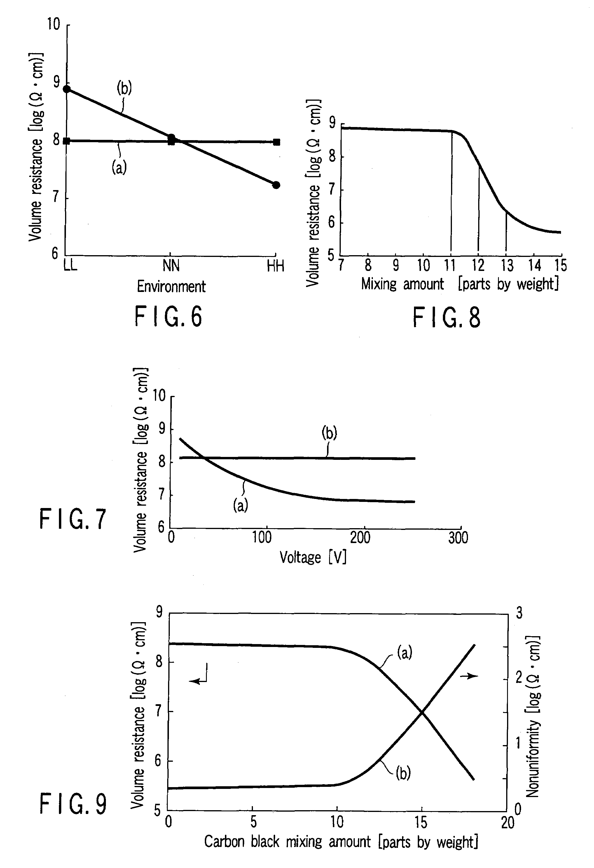
[0112]A charging roll was prepared as in Example 1 by using the composition No. 9 shown in Table 2, except that the mixing amount of the electrically conductive composite rubber powder was varied. The charging roll for Example 2 was found to exhibit a hardness of 64°, a volume resistance under the NN environment of 8.11 log(Ω·cm), a dependency of the resistance on the environment, i.e., the difference between the value under the LL environment and the value under the HH environment, of 0.43 log(Ω·cm), and a dependency of the resistance on voltage, i.e., the difference between the value under the voltage of 10V and the value under the voltage of 250V, of 0.38 log(Ω·cm). Also, the difference between the maximum value and the minimum value of the resistance within the roll was found to be 0.38 log(Ω·cm).

[0113]In the next step, a printing test was conducted as in Example 1 by applying a voltage of 1,000V with the charging roll thus prepared used as the charging roll 2 included in the el...

example 3

[0114]A charging roll was prepared by using a resin powder having an electronic conductivity, instead of the composite conductive rubber powder used in composition No. 9 shown in Table 2. The electrically conductive resin powder was prepared by the steps given below:

[0115]1) Mixing was performed in a Shinagawa mixer with the composition B shown in Table 3, i.e., vinyl chloride (trade name of Zest P-21 manufactured by Zeon corporation), magnesium stearate, Seast 3 and the half amount of DOP.

[0116]2) In the next step, the remaining half amount of DOP was added bit by bit to the mixture that was sufficiently mixed in step 1) so as to prepare a paste.

[0117]3) Then, the paste was poured into a mold having a core metal arranged therein, followed by thermally curing the paste at 160° C. for 180 minutes.

[0118]4) Further, after the cooling, the molded material was released from the mold so as to obtain an electrically conductive resin roll.

[0119]5) Still further, the resin roll was ground so...


PUM

PropertyMeasurementUnit
sizeaaaaaaaaaa
volume resistivityaaaaaaaaaa
particle diameteraaaaaaaaaa

Abstract

Disclosed is an electrically conductive member, comprising a substrate of a metal or a resin and an electrically conductive elastic layer formed to cover the substrate, wherein the electrically conductive elastic layer is formed of a rubber elastic body prepared by dispersing at least an electrically conductive powder used as a conductive agent into a rubber compound, followed by vulcanizing the rubber compound, the electrically conductive powder being obtained by curing and powdering an electrically conductive rubber compound or an electrically conductive resin mixture.

Description

CROSS-REFERENCE TO RELATED APPLICATIONS[0001]This application is based upon and claims the benefit of priority from prior Japanese Patent Application No. 2003-414755, filed Dec. 12, 2003, the entire contents of which are incorporated herein by reference.BACKGROUND OF THE INVENTION[0002]1. Field of the Invention[0003]The present invention relates to an electrically conductive member, particularly, to an electrically conductive member used in at least one of the transfer roll, the charging roll, the developing roll, the cleaning roll, the transfer belt, the intermediate transfer belt and the intermediate transfer drum arranged around the photosensitive drum (image carrier) included in an electrophotographic printing apparatus such as a copier, a printer, or a facsimile machine.[0004]2. Description of the Related Art[0005]As known in the art, an electrophotographic printing apparatus such as a copier, a printer or a facsimile machine is constructed as shown in FIG. 1. Reference numeral...

Claims


Application Information

Patent Timeline
Patent Type & Authority Patents(United States)
IPC IPC(8): B32B5/22B32B27/38B32B5/16G03G15/00F16C13/00G03G15/02G03G15/08G03G15/16G03G21/10H01B1/00
CPCG03G15/1685Y10T428/254Y10T428/249987Y10T428/249986Y10T428/31529Y10T428/31511
Inventor ONUKI, AKIONISHIYA, KOJI
Owner KINOYOSHA CO LTD
Why Eureka
Try Eureka