Fixing device and image forming apparatus
a fixing device and image forming technology, applied in the field of fixing devices and image forming apparatuses, can solve the problems of many parts of the fixing device, inability to completely prevent and the inability to fix the recording medium, so as to improve the precision stability of the fixing device attached to and detachable from the image forming apparatus body, and suppress the wrinkles of the recording medium
- Summary
- Abstract
- Description
- Claims
- Application Information
AI Technical Summary
Benefits of technology
Problems solved by technology
Method used
Image

Examples
first embodiment
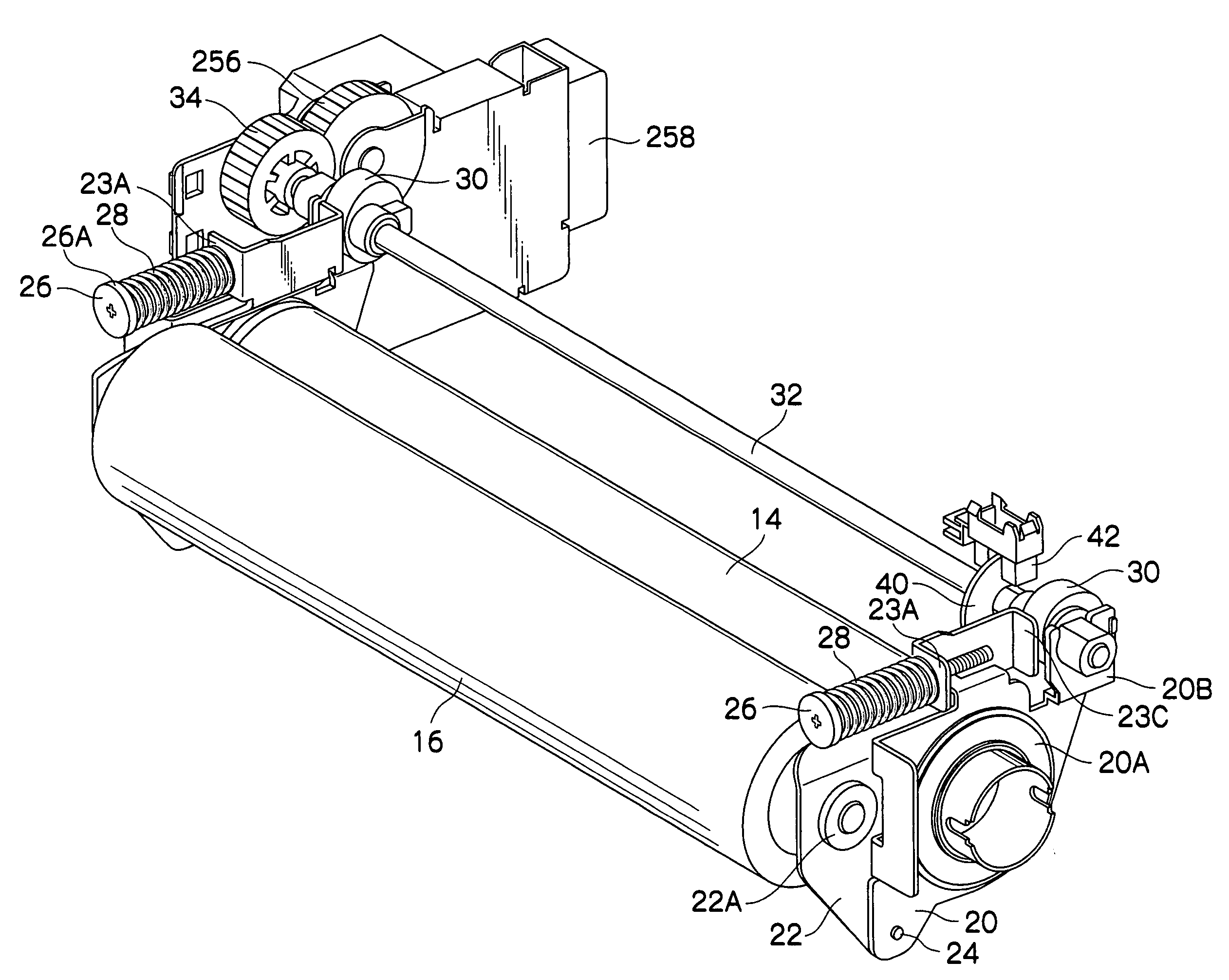
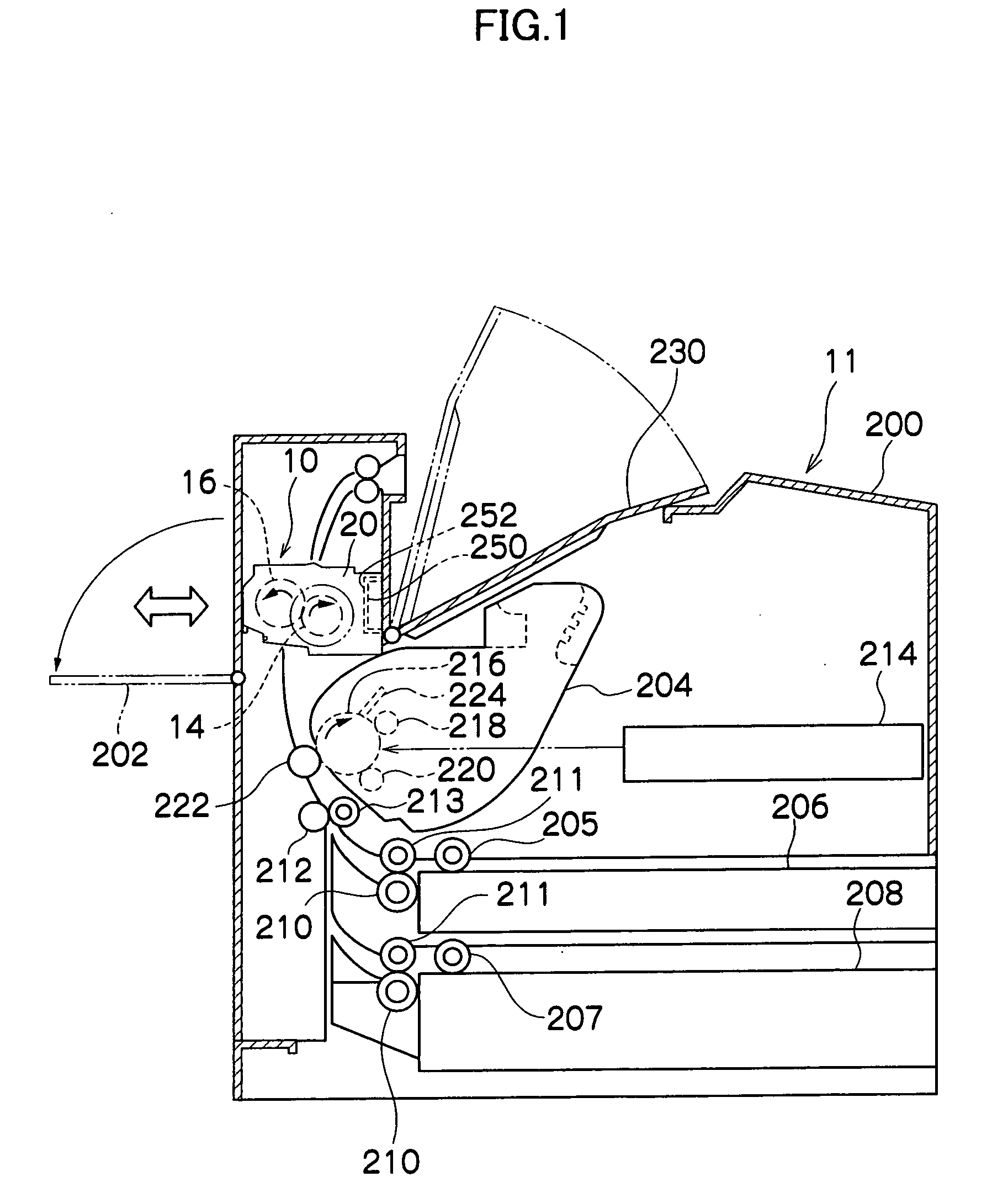
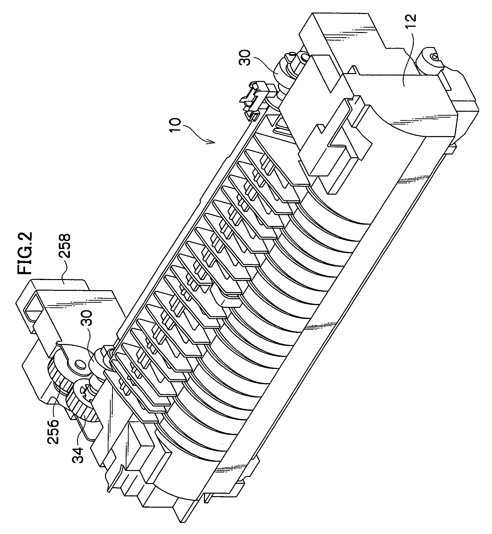
[0077]FIG. 1 shows an image forming apparatus 11 to which a fixing device 10 pertaining to a first embodiment of the invention has been applied.
[0078] The image forming apparatus 11 includes an image forming apparatus body 200. The fixing device 10 comprises a unit that is attachable to and detachable from the image forming apparatus body 200. An open / close cover 202 is disposed on the image forming apparatus body 200, and the fixing device 10 is loaded into the image forming apparatus body 200 as a result of the open / close cover 202 being opened.
[0079] When the fixing device 10 is loaded into the image forming apparatus body 200, a connector 252 of the fixing device 10 becomes connected to a connector 250 of the image forming apparatus body 200, such that power can be supplied to the fixing device 10 and the completion of the loading of the fixing device 10 is detected. After the fixing device 10 has been loaded into the image forming apparatus body 200, the image forming apparat...
second embodiment
[0118] Next, a fixing device of a second embodiment of the invention will be described.
[0119] The same reference numerals will be given to members that are the same as those in the first embodiment, and redundant description of those same members will be omitted.
[0120] As shown in FIG. 11, the fixing device includes pressuring levers 62 that retain the pressuring roller 16 and are pivotably supported on brackets 60 that retain the heating roller 14. End portions 66A of tension springs 66 are attached to guide members 62A of the pressuring levers 62. Groove portions 64A are formed in the peripheral surfaces of cams 64 disposed on retaining members 60B of the brackets 60, and hooks 66B formed on the other end portions of the tension springs 66 are hooked in the groove portions 64A. The pressuring levers 62 are pulled toward the brackets 60 by the tension springs 66, whereby the pressuring roller 16 is pushed against the heating roller 14.
[0121] The load of the pressurizing roller 1...
third embodiment
[0122] Next, a fixing device of a third embodiment of the invention will be described.
[0123] The same reference numerals will be given to members that are the same as those in the first and second embodiments, and redundant description of those same members will be omitted.
[0124] As shown in FIG. 12 and FIGS. 13A and 13B, in this fixing device, groove portions 74A are formed in the outer peripheries of cams 74 supported in retaining members 60B, and bearings 76 are disposed in the groove portions 74A. The hooks 66B of the tension springs 66 are hooked onto the bearings 76.
[0125] In this fixing device, because the hooks 66B of the tension springs 66 are hooked onto the bearings 76, the sliding resistance between the cams 74 and the hooks 66B becomes smaller when the cams 74 rotate.
PUM
 Abstract
Description
Claims
Application Information
 - R&D
- Intellectual Property
- Life Sciences
- Materials
- Tech Scout
- Unparalleled Data Quality
- Higher Quality Content
- 60% Fewer Hallucinations
Browse by: Latest US Patents, China's latest patents, Technical Efficacy Thesaurus, Application Domain, Technology Topic, Popular Technical Reports.
© 2025 PatSnap. All rights reserved.Legal|Privacy policy|Modern Slavery Act Transparency Statement|Sitemap|About US| Contact US: help@patsnap.com