Conveying device and image forming apparatus

a technology of conveying device and image forming apparatus, which is applied in the direction of printing, other printing apparatus, etc., can solve the problems of paper deformation (curl), large creases at the tail portion (trailing edge portion) of the paper, and the output product quality is affected, so as to achieve stable conveying of recording medium and suppress wrinkles and creases

Inactive Publication Date: 2012-07-26
FUJIFILM CORP
View PDF5 Cites 11 Cited by
  • Summary
  • Abstract
  • Description
  • Claims
  • Application Information

AI Technical Summary

Benefits of technology

[0011]In consideration of the above circumstances, the present invention provides a conveying device and an image forming apparatus capable of stably conveying a recording medium, even when conveying the recording medium with the printed front-face thereof facing down after an image has been formed by jetting liquid droplets, and capable of suppressing generation of wrinkles and creases in the recording medium.

Problems solved by technology

However, problems of paper deformation (curl) arise when paper that is not of inkjet-specification, such as ordinary coated printing paper and standard plain paper, is employed as the recording medium in an inkjet recording apparatus, and in particular when an ink with water as a solvent is jetted.
Obviously curl is detrimental to output product quality, however there is also the possibility that minute undulations, at a level not discernible by user eye, that occurred when printing the front face subsequently result in the generation of large creases at a tail portion (trailing edge portion) of the paper when printing the back face of the paper.
However, when the method of the above document is applied for conveying a paper with a reverse-face thereof facing upward after an image has already been formed on a front-face of the paper by inkjet heads on large size paper (for example Half Kiku size (636 mm×469 mm) or B2 size paper), it is known that the two end portions of the press roller still press the paper, even if only weakly (see paragraph number ), resulting in creases being induced at the central portion of the paper.

Method used


Image

  • Conveying device and image forming apparatus
  • Conveying device and image forming apparatus
  • Conveying device and image forming apparatus

Examples


Embodiment Construction

[0049]Explanation follows regarding an example of an exemplary embodiment of the present invention, with reference to the drawings.

[0050]Overall Configuration

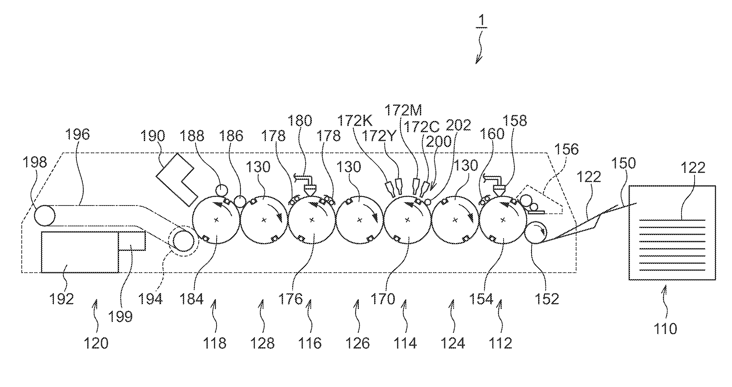
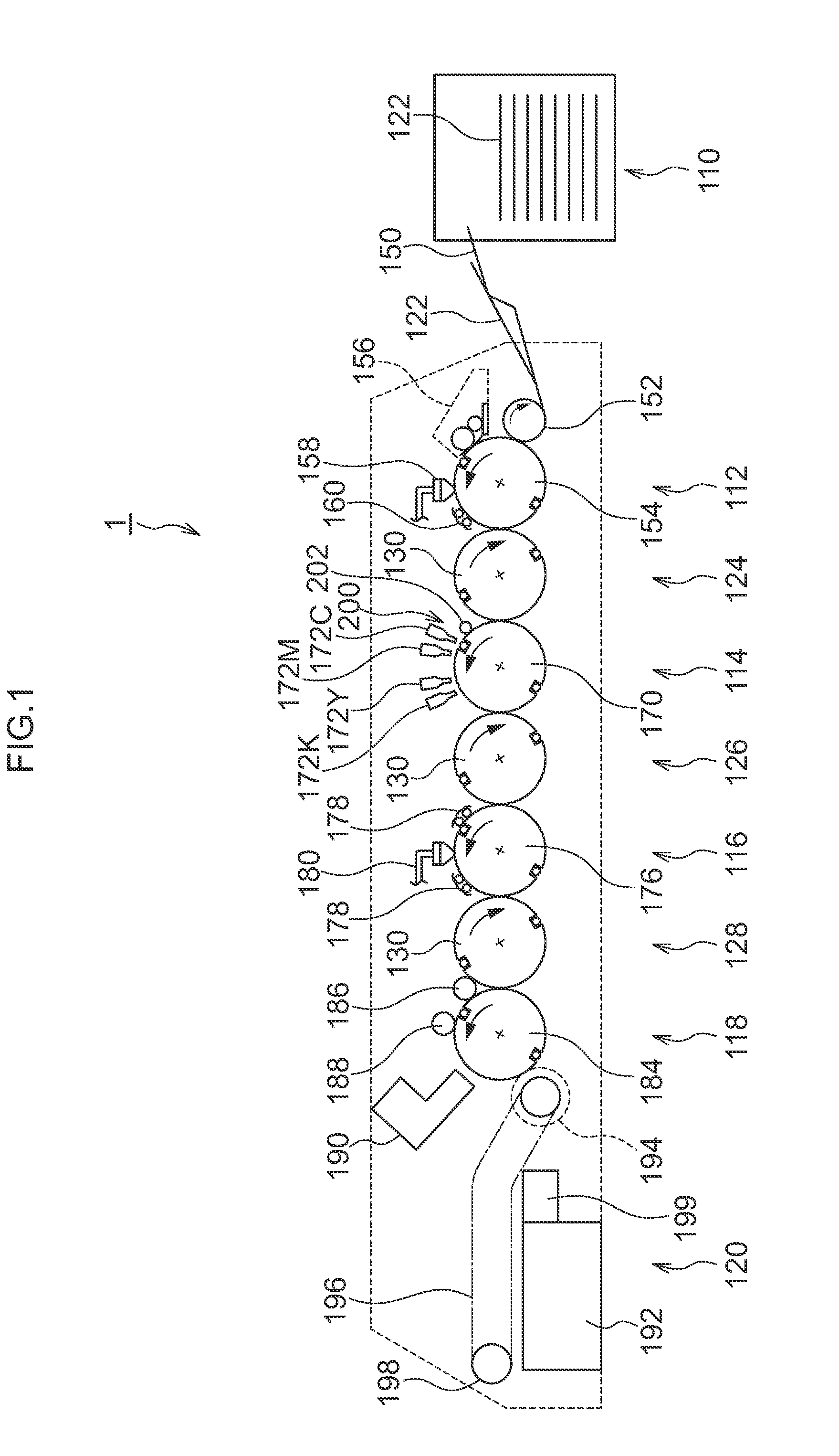
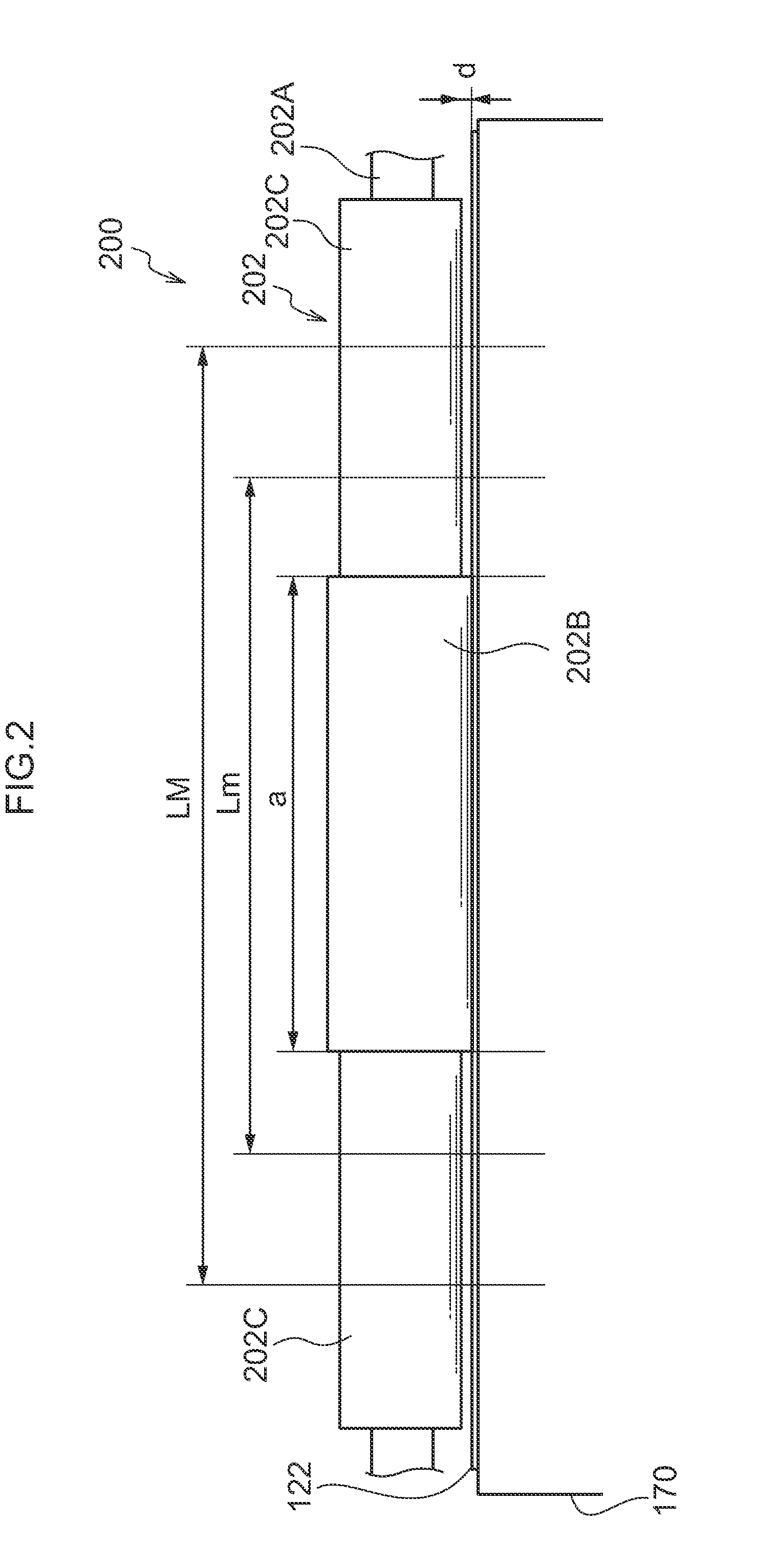
[0051]Explanation follows regarding an example of a configuration of an inkjet image forming apparatus for implementing the conveying device and the image forming apparatus of the present invention, with reference to FIG. 1 and FIG. 2. FIG. 1 is a schematic diagram (side view) illustrating the apparatus overall, and FIG. 2 is a configuration diagram focusing on a press roller.

[0052]An inkjet recording apparatus 1 utilizes an impression cylinder direct rendering method to form a desired color image by jetting plural colors of ink (liquid droplets) from inkjet heads 172M, 172K, 172C, 172Y, serving as examples of liquid droplet jetting heads, onto paper 122 retained on an impression cylinder (image rendering drum 170) in an image rendering section 114. The inkjet recording apparatus 1 is an on-demand type of image forming apparatu...


PUM


Abstract

A conveying device comprising a conveying body that conveys a recording medium; and a press roller comprising a large diameter portion that is formed at an axial direction central portion of the press roller and makes contact with the conveying body, and small diameter portions formed at both axial direction sides of the large diameter portion with a smaller diameter than the large diameter portion. Only a width direction central portion of the recording medium is pressed against the conveying body by the large diameter portion.

Description

CROSS-REFERENCE TO RELATED APPLICATION[0001]This application is claims priorities under 35 USC 119 from Japanese Patent Application No. 2011-013316 filed on Jan. 25, 2011, the disclosure of which is incorporated by reference herein.BACKGROUND OF THE INVENTION[0002]1. Technical Field[0003]The present invention relates to a conveying device and an image forming apparatus.[0004]2. Related Art[0005]An image forming apparatus is known that conveys a recording medium, such as paper, and jets ink droplets onto the recording medium using an inkjet recording head.[0006]In such an image forming apparatus it is necessary to have a small separation distance between the recording medium and the inkjet recording head (for example maintain the separation distance at about 1 mm or less). Consequently, a mechanism is required for retaining the recording medium on a conveying unit (such as a belt or drum), particularly when forming images at high speed.[0007]However, problems of paper deformation (cu...

Claims


Application Information

Patent Timeline
Patent Type & Authority Applications(United States)
IPC IPC(8): B41J2/01
CPCB41J11/002B41J13/226B41J13/076B41J11/0022B41J11/00216B41J11/0024
Inventor YAMANOBE, JUN
Owner FUJIFILM CORP
Why Eureka
Try Eureka