Light source device and display apparatus

a technology of light source device and display apparatus, which is applied in the direction of lighting and heating apparatus, instruments, optical elements, etc., can solve the problems that the wrinkles on the expanded optical sheet cannot be prevented, and achieve the effect of suppressing wrinkles on the optical sheet and avoiding deterioration in display quality

Inactive Publication Date: 2016-07-07
SAKAI DISPLAY PROD
View PDF6 Cites 12 Cited by
  • Summary
  • Abstract
  • Description
  • Claims
  • Application Information

AI Technical Summary

Benefits of technology

[0024]According to the embodiment of the present invention, even in the case where the optical sheet is expanded when the light source emits light, wrinkles occurring on the optical sheet can be suppressed, which can avoid deterioration in the display quality caused by the occurrence of wrinkles on the optical sheet.

Problems solved by technology

It is therefore difficult, in the configuration disclosed in Japanese Patent Application Laid-Open No. 2008-58709, to ensure a space where a pressing member which presses the optical sheet can sufficiently be deformed in order to prevent the occurrence of wrinkles on the expanded optical sheet.
If the pressing member is not sufficiently deformed, such a problem is caused that wrinkles on the expanded optical sheet cannot be prevented from occurring.

Method used


Image

  • Light source device and display apparatus
  • Light source device and display apparatus
  • Light source device and display apparatus

Examples


embodiment 1

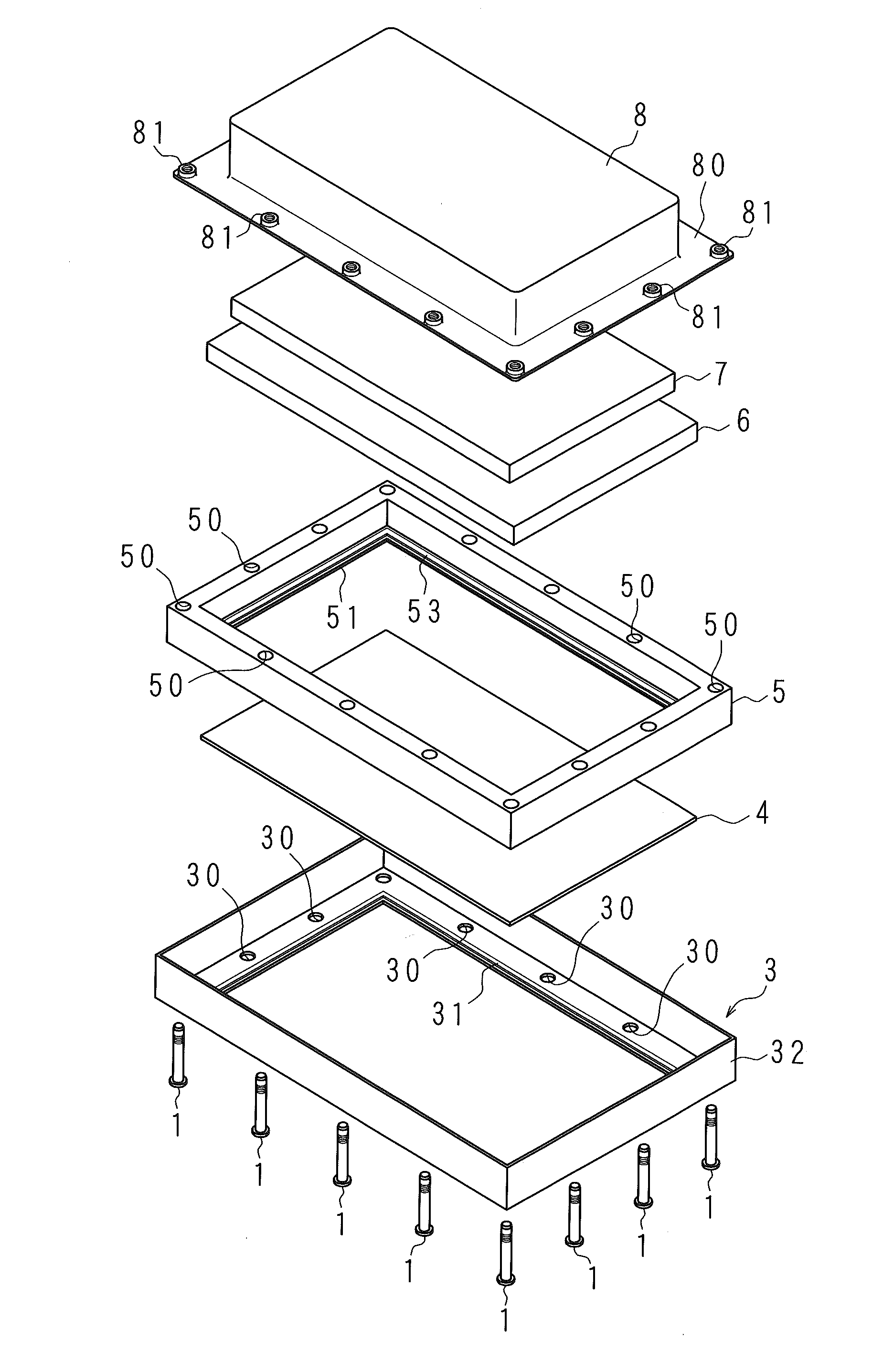
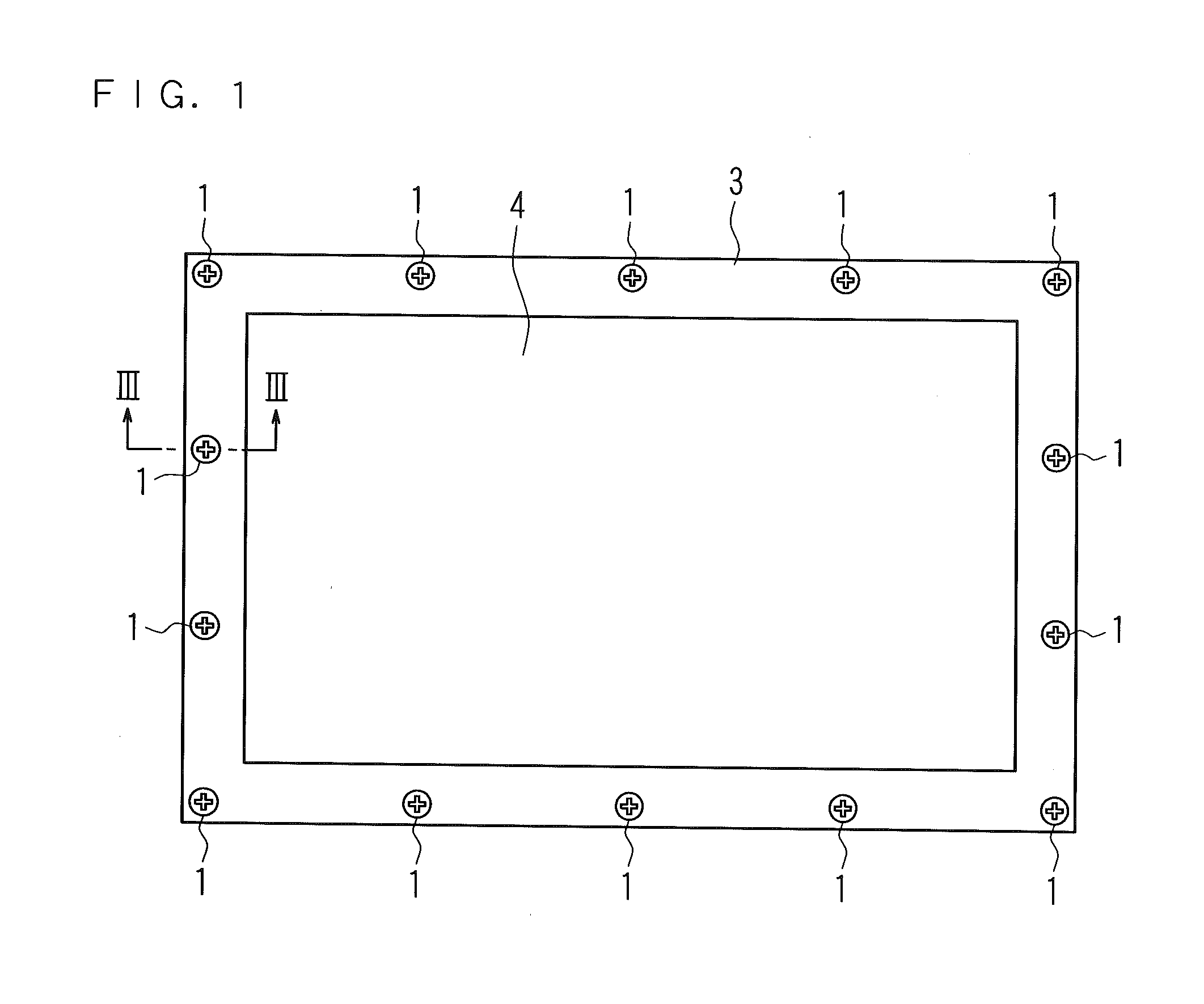
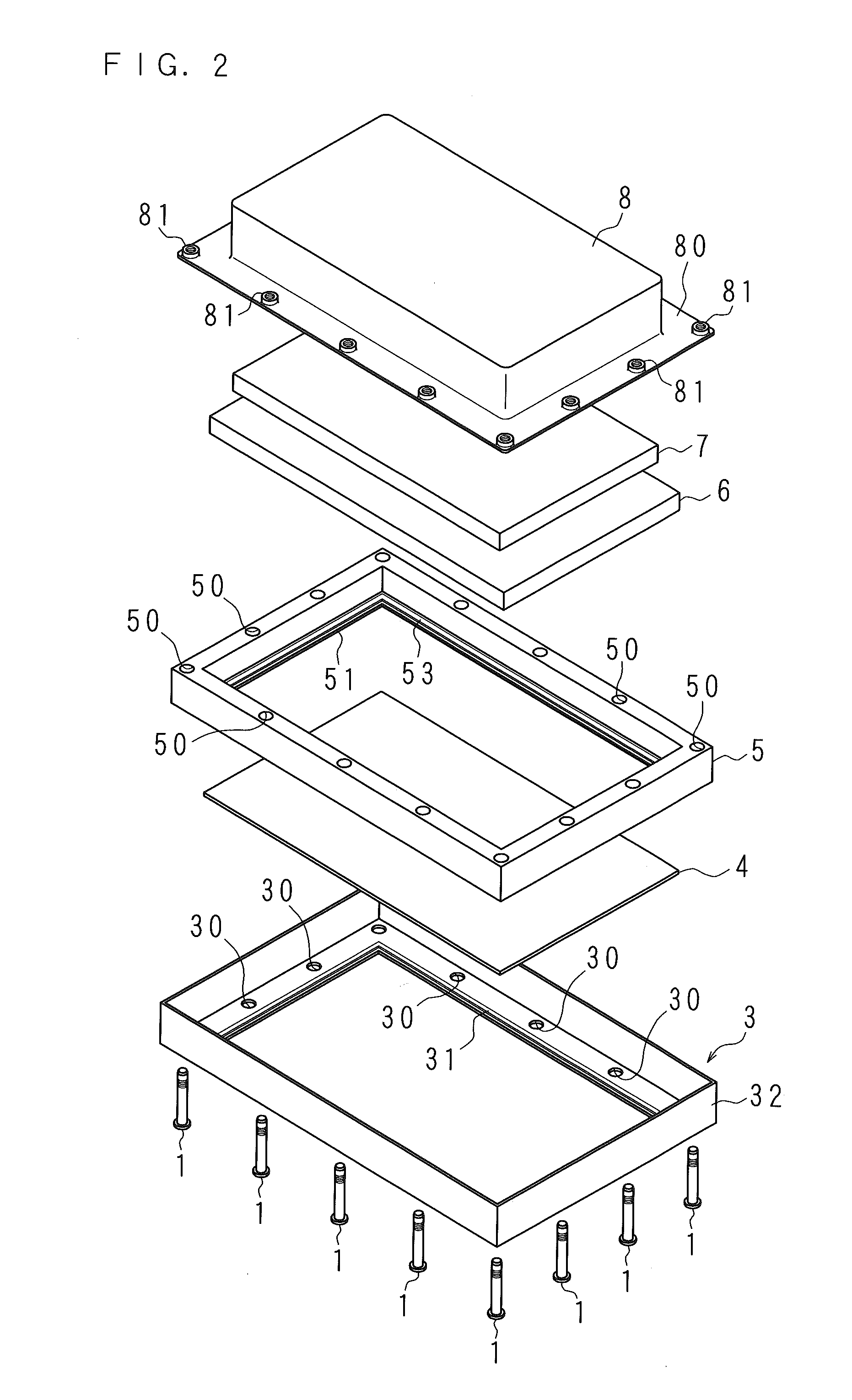
[0040]FIG. 1 is a front view of a display apparatus according to Embodiment 1. FIG. 2 is an exploded perspective view illustrating a configuration of major components of the display apparatus according to Embodiment 1. The display apparatus according to Embodiment 1 is a liquid crystal display apparatus including a liquid crystal panel (display panel) 4 having the shape of a rectangular plate, and a direct type light source device which irradiates the liquid crystal panel 4 with light.

[0041]As illustrated in FIG. 2, the display apparatus of Embodiment 1 is constituted by a bezel 3, the liquid crystal panel 4, a panel chassis 5, an optical sheet 6, a light source unit 7 and a backlight chassis (hereinafter referred to as a BL chassis) 8 that are layered in this order and are connected as will be described later by multiple connecting members 1.

[0042]The bezel 3 has a shape of a rectangular frame and has a plate part 32 vertically protruding from the outer peripheral edge of the bezel...

embodiment 2

[0067]A display apparatus according to Embodiment 2 will be described below. In the display apparatus according to Embodiment 2, the configuration of a connecting member connecting the bezel 3, the panel chassis 5 and the BL chassis 8 is different from that of the display apparatus according to Embodiment 1 described above. Thus, only the connecting member is described while the other components will be denoted by the same reference numerals as those in Embodiment 1 and thus will not be described in detail.

[0068]FIG. 7 and FIG. 8 are perspective views illustrating the configuration of the connecting member according to Embodiment 2. FIG. 9 and FIG. 10 are cross-sectional views taken along the line III-III in FIG. 1. FIGS. 7 and 9 illustrate the state where the display apparatus is not in operation, whereas FIGS. 8 and 10 illustrate the state where the display apparatus is in operation.

[0069]A connecting member 9 of Embodiment 2 is constituted by one member. The connecting member 9 o...


PUM

PropertyMeasurementUnit
temperatureaaaaaaaaaa
shapeaaaaaaaaaa
thicknessaaaaaaaaaa

Abstract

Provided are a light source device capable of suppressing the occurrence of wrinkles on an optical sheet even if the optical sheet expands due to heat generated at the time of light emission, and a display apparatus including the light source device. In the light source device, an optical sheet is disposed with one surface facing the light source unit, while the light source unit and the optical sheet are supported by a support member. A contact portion being in contact with the peripheral edge part of the other surface of the optical sheet is pressed to the optical sheet by a connecting member, and the optical sheet is held between the contact portion and the support member. The contact portion and the support member holding the optical sheet are connected with each other by the connecting member. The connecting member is configured to have a weakened force of pressing the contact portion if a surrounding temperature reaches a predetermined temperature or higher.

Description

CROSS-REFERENCE TO RELATED APPLICATION[0001]This application is the national phase under 35 U.S.C. §371 of PCT International Application No. PCT / JP2014 / 071551 which has an International filing date of Aug. 18, 2014 and designated the United States of America.BACKGROUND[0002]1. Technical Field[0003]The present invention relates to: a light source device used as a light source of a display apparatus such as a liquid crystal display apparatus; and a display apparatus including the light source device.[0004]2. Description of Related Art[0005]In recent years, display apparatuses such as liquid crystal displays and liquid crystal televisions have widely been spread. A display apparatus includes a rectangular plate-shaped display panel which has a display surface at the front side on which an image is displayed, and a light source device disposed at the rear side of the display panel to irradiate the display panel with light. An example of the light source device includes a direct type lig...

Claims


Application Information

Patent Timeline
Patent Type & Authority Applications(United States)
IPC IPC(8): G02F1/1335F21V17/12F21V3/02F21V29/00
CPCG02F1/133608F21V29/00G02F1/133606F21V3/02F21V17/12G02B5/0278G02F2201/54G02B5/02
Inventor FUKAI, HIROKI
Owner SAKAI DISPLAY PROD
Why Eureka
Try Eureka