
Large-diameter corrugated pipe vibration forming device and method

A vibrating device and bellows technology, applied in the field of large-diameter bellows forming devices, can solve the problems of unstable processing quality, inability to guarantee the quality of forming, and large changes in the wall thickness of the bellows, and improve dimensional stability and surface quality. , The effect of inhibiting the wrinkling and cracking of the pipe and increasing the surface finish

Active Publication Date: 2016-10-26
YANSHAN UNIV
View PDF5 Cites 9 Cited by
  • Summary
  • Abstract
  • Description
  • Claims
  • Application Information

AI Technical Summary

Problems solved by technology

[0003] Long-term production practice has proved that although mechanical forming, especially rolling forming, can realize the production of large wave and high corrugated pipes, the processing quality is unstable and is greatly affected by the technical level of the operator. There are local stress and uneven surface hardening phenomenon; although rubber forming can realize axial compression to compensate the material in the deformation zone, the wall thickness does not change much, and the wave size is stable, but it cannot realize the production of large wave and high bellows; Although the forming can realize the production of large corrugated high corrugated pipes and the corrugated pipe surface is not easy to produce surface quality problems such as scratches, the production efficiency is high, especially the multi-wave one-time forming, but the wall thickness of the corrugated pipe varies greatly and the wave size is unstable, which is very difficult. It is easy to appear that the forming size does not meet the requirements
In short, none of the existing forming methods for large wave and high bellows can guarantee the quality of its forming

Method used


Image

  • Large-diameter corrugated pipe vibration forming device and method
  • Large-diameter corrugated pipe vibration forming device and method
  • Large-diameter corrugated pipe vibration forming device and method

Examples


Embodiment Construction

[0025] Below in conjunction with accompanying drawing and embodiment the present invention will be further described:

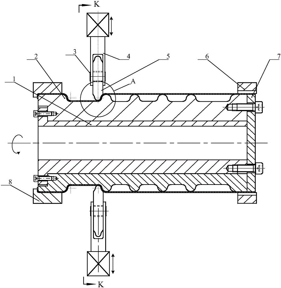
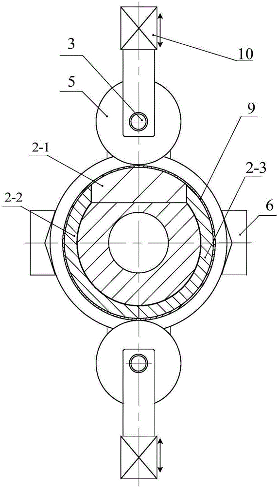
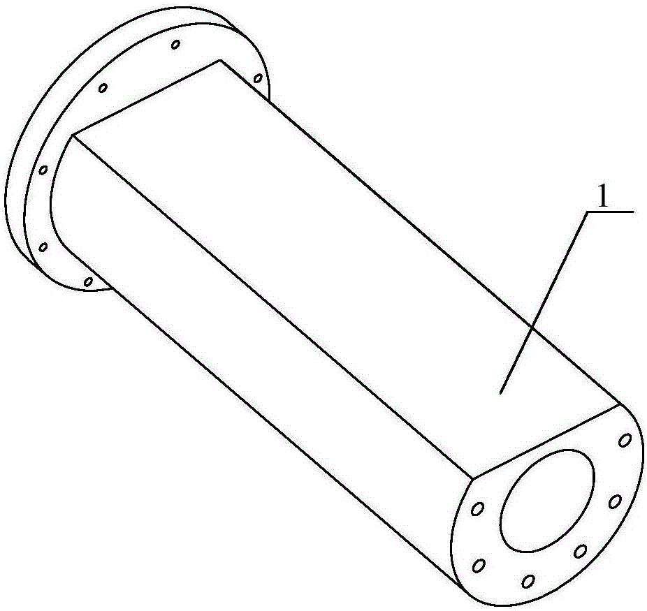
[0026] like Figure 1~2 As shown, a large-diameter corrugated pipe vibration forming device according to the embodiment of the present invention is mainly composed of a mandrel 1, a corrugated mandrel 2, a support frame 4, a forming wheel 5, a connecting plate 7, and a vibration device 10. The corrugated mandrel 2 It is fitted on the mandrel 1 and connected to form an integral mold through the flange at the bottom of the mandrel 1 and the connection plate 7 at the end, and the pipe 9 is fitted outside the corrugated mandrel 2 . The two ends of the tube blank 9 are provided with a left end jaw 8 and a right end jaw 6 for clamping and fixing. A total of 4 left-end jaws and 4 right-end jaws are evenly distributed at both ends of the tube blank. The forming wheel 5 and the support frame 4 are installed through the rotating shaft 3 . A vibration device 9 is ins...


PUM


Abstract

The invention discloses a large-diameter corrugated pipe vibration forming device and a method. The forming device mainly consists of a mandrel, a corrugated core mold, a connecting disc, forming wheels, a support frame and a vibrating device. The corrugated core mold coats the mandrel, and is connected with a flange at the bottom of the mandrel and the connecting disc at the end part to form an integral mold. A pipe blank coats the outer surface of the corrugated core mold; left and right end clamping jaws are arranged at the two end parts of the pipe blank; and the forming wheels are distributed on the outer side of the pipe blank. After the clamping jaws clamp the pipe blank, the pipe blank rotates around the axis, the vibration excitation is applied to the forming wheels, and the forming wheels radially and axially feed the pipe blank. All traditional forming processes are synthesized; the friction force between the metal pipe blank and the forming mold is effectively reduced by a vibration exciting device; and when high-frequency vibration excitation is applied, the deformation resistance of the metal pipe blank can be reduced, the corrugation and breakage generation and development of the pipe blank are inhibited, the size precision of large-wave high corrugated pipes is guaranteed, and the surface smoothness of formed workpieces is increased.

Description

technical field [0001] The invention relates to the processing of metal pipes, in particular to a large-diameter corrugated pipe forming device and method. Background technique [0002] Metal bellows can be used as compensation and shock absorbing elements to absorb thermal expansion and contraction and dimensional changes caused by vibration, and have been widely used in instrumentation, aviation, micro motors, petrochemical and automotive industries. Metal bellows is processed from straight pipes, and its main forming methods include: mechanical forming, rubber forming (elastic mold forming), hydraulic forming, and welding forming. Among them, mechanical forming includes rolling forming and spinning forming. [0003] Long-term production practice has proved that although mechanical forming, especially rolling forming, can realize the production of large wave and high corrugated pipes, the processing quality is unstable and is greatly affected by the technical level of the...

Claims


Application Information

Patent Timeline
IPC IPC(8): B21D15/06
CPCB21D15/06
Inventor 曹秒艳赵长财董国疆左苗苗王鹏
Owner YANSHAN UNIV
Learn More