
A device for damping vibration of a ring for axially retaining turbomachine fan blades

a technology of axial retention ring and fan blade, which is applied in the direction of machines/engines, mechanical equipment, liquid fuel engines, etc., can solve the problems of fan blade mounting that raises numerous problems, wear on the axial retention ring and on the rotary disk, and the top of the crenellation is affected, so as to achieve the effect of reducing such drawbacks

Active Publication Date: 2007-01-25
SN DETUDE & DE CONSTR DE MOTEURS DAVIATION S N E C M A
View PDF5 Cites 29 Cited by
  • Summary
  • Abstract
  • Description
  • Claims
  • Application Information

AI Technical Summary

Benefits of technology

[0004] A main object of the present invention is thus to mitigate such drawbacks by proposing a device for damping the vibration to which the ring for axially retaining fan blades is subject.
[0006] By adding contact surfaces with the axial retention ring and the disk flange, the device of the invention serves to modify the natural modes of vibration of the retention ring. In addition, since the device is constituted by an element made of elastomer material, its surfaces that come into contact with the retention ring and the disk flange tend, under the centrifugal effect, to become pressed against the retention ring and the flange. Thus, the vibration to which the retention ring is subject is damped and any risk of wear is avoided. The use of such a damper device can also serve to block the retention ring tangentially around the disk flange.

Problems solved by technology

In practice, that type of fan blade mounting raises numerous problems.
In particular, wear is observed on the axial retention ring and on the rotary disk.
The wear is mainly caused by the vibration to which the axial retention ring is subject during rotation of the disk.
In particular, rotation of the disk leads to small movements of the axial retention ring, causing wear on the tops of the crenellations of the annular flange for holding the ring on the disk.

Method used


Image

  • A device for damping vibration of a ring for axially retaining turbomachine fan blades
  • A device for damping vibration of a ring for axially retaining turbomachine fan blades
  • A device for damping vibration of a ring for axially retaining turbomachine fan blades

Examples


Embodiment Construction

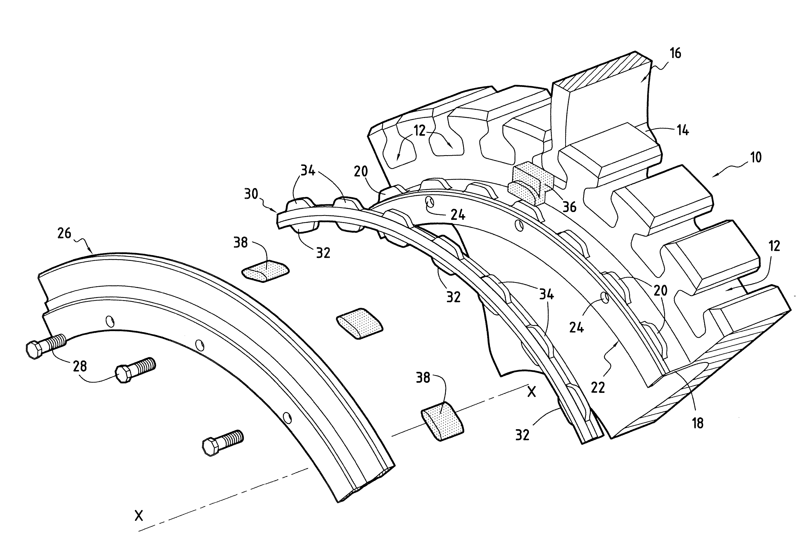
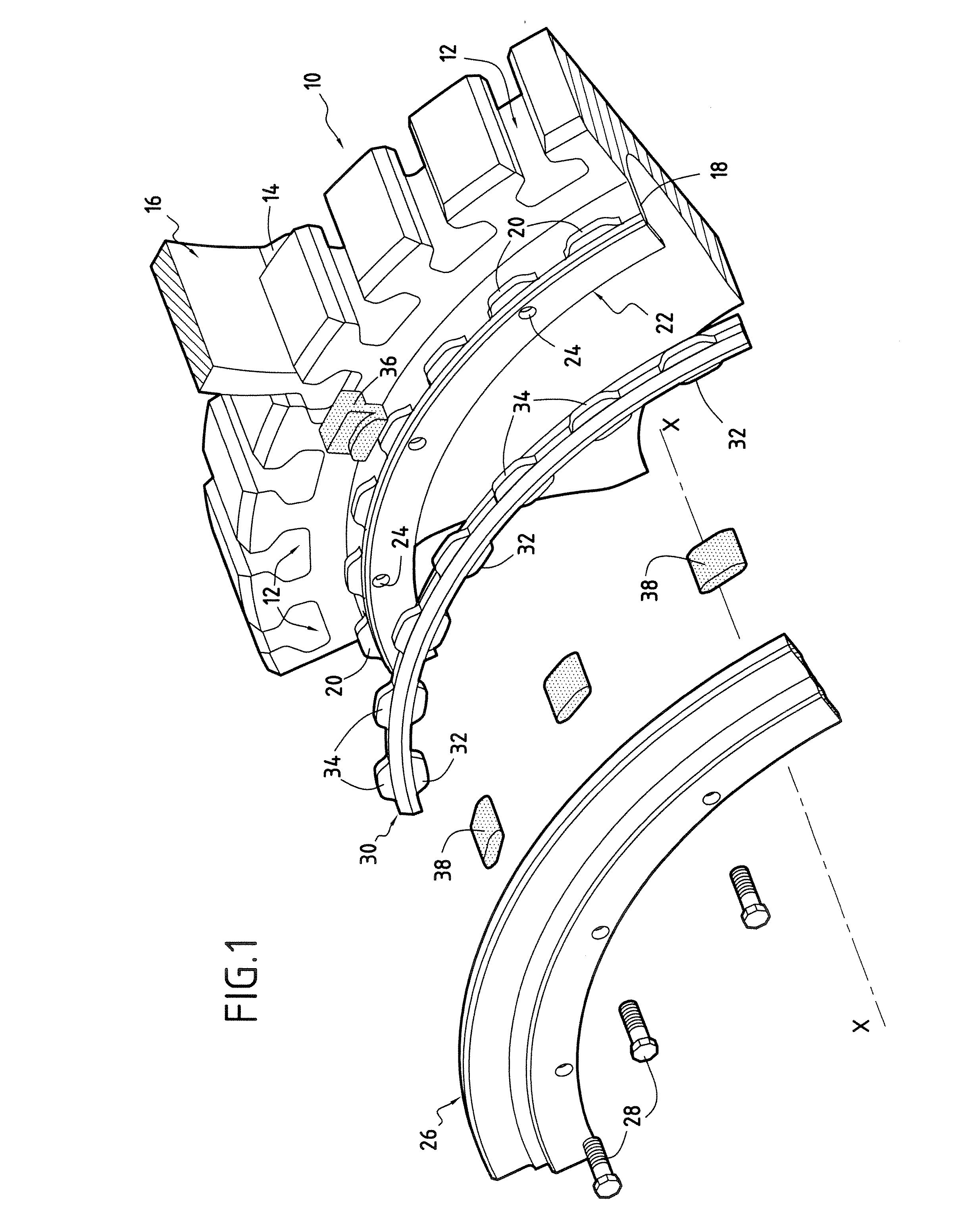
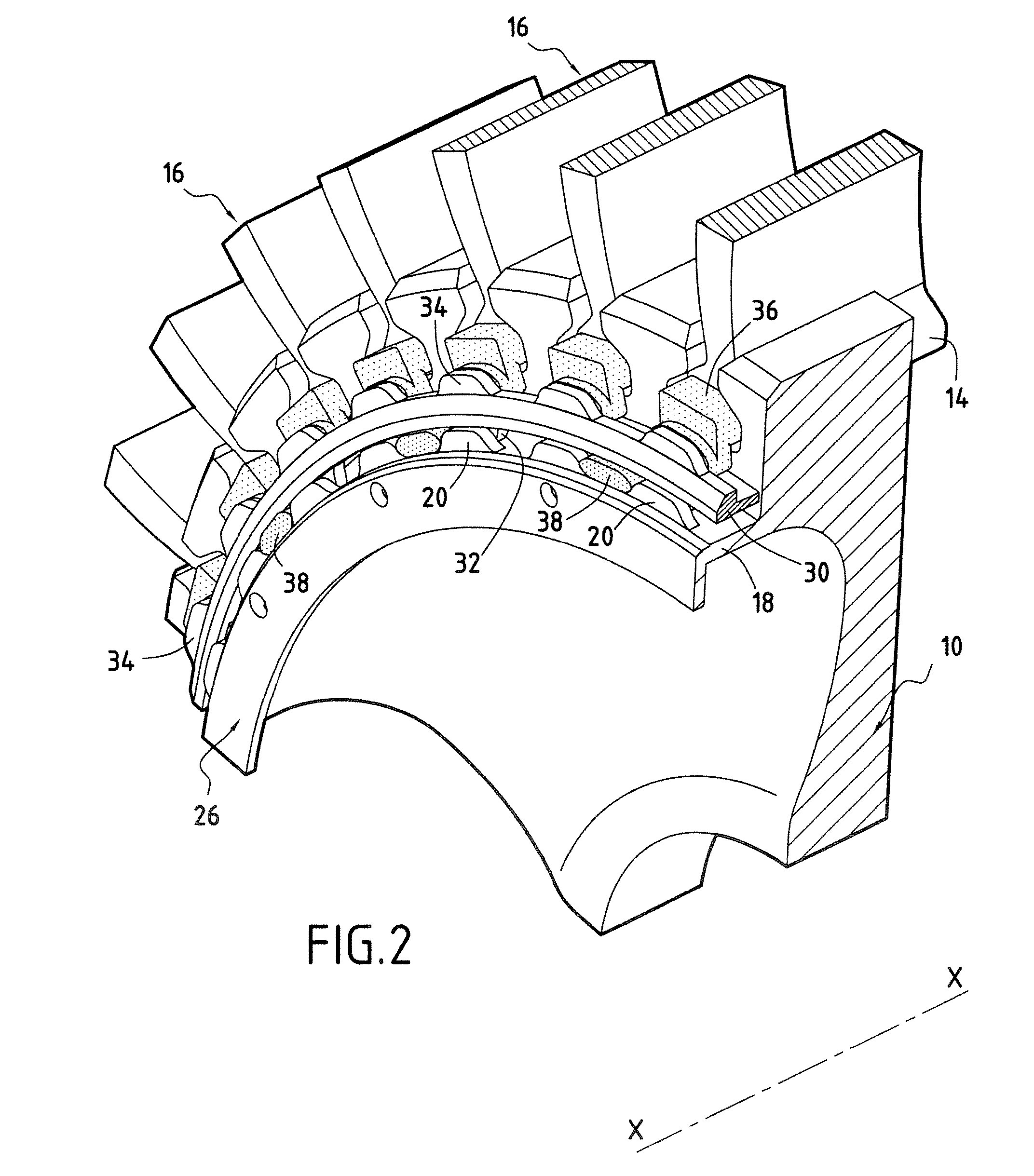
[0018]FIGS. 1 and 2 show a portion of a turbomachine fan disk 10. The disk 10 is suitable for rotating about a longitudinal axis X-X of the turbomachine.

[0019] The rotary disk 10 includes a plurality of slots 12 that are regularly distributed around its outer circumference, each slot being designed to receive the root 14 of a fan blade 16 (only one blade is shown in part in FIG. 1). More precisely, the root 14 of each blade 16 is dovetail-shaped and is engaged axially in a corresponding one of the slots 12 that are provided for this purpose.

[0020] The rotary disk 10 also has an annular flange 18 extending axially upstream. At its end remote from the disk, the flange 18 is provided with a plurality of outer crenellations (or teeth) 20 which extend radially outwards relative to the disk and which are regularly distributed around the entire circumference of the disk.

[0021] It should be observed that the number of outer crenellations 20 on the flange 18 is identical to the number of ...


PUM

PropertyMeasurementUnit
Shapeaaaaaaaaaa
Hardnessaaaaaaaaaa

Abstract

A device for damping vibration of a retention ring for axially retaining turbomachine fan blades, the blades being designed to be mounted via their roots on a rotary disk having an annular flange extending axially and provided with a plurality of radial crenellations for coming into contact with a plurality of complementary radial crenellations of a retention ring designed to be mounted around the disk flange, the device comprising an abutment element of elastomer material designed to be received axially between two adjacent crenellations of the flange and two adjacent complementary crenellations of the retention ring, and radially between the flange of the rotary disk and the retention ring, said abutment element presenting contact surfaces for coming into contact with the adjacent crenellations, with the retention ring, and with the flange of the rotary disk.

Description

BACKGROUND OF THE INVENTION [0001] The present invention relates to the general field of mounting fan blades on a rotary disk of a turbomachine. The invention relates more particularly to a device serving to damp the vibration to which the ring for axially retaining the fan blades is subjected. [0002] The fan of a turbomachine typically comprises a plurality of blades mounted on a rotary disk via blade roots which are received in slots in the disk. In certain technologies for mounting fan blades, a ring is also placed around an annular flange extending axially from the upstream side of the rotary disk. Such a ring is held axially against the flange via crenellations formed around the entire circumference thereof. The ring is also mounted in axial abutment against the roots of the blades so as to retain said roots axially. [0003] In practice, that type of fan blade mounting raises numerous problems. In particular, wear is observed on the axial retention ring and on the rotary disk. T...

Claims


Application Information

Patent Timeline
IPC IPC(8): F04D29/66
CPCF01D5/26F01D5/3007F01D5/326F01D25/04F05D2300/431F04D29/668F05D2250/182F05D2260/30F04D29/322
Inventor FORGUE, JEAN-BERNARDLAUVERGNAT, JACK-PIERRELOISEAU, HENRY LOUIS PAUL NICOLASMONNET, DIDIERNITRE, THIERRYREGHEZZA, PATRICK JEAN-LOUIS
Owner SN DETUDE & DE CONSTR DE MOTEURS DAVIATION S N E C M A
Learn More