NVH and gas pulsation reduction in AC compressor

a compressor and gas pulsation technology, which is applied in the field of compressors and pumps, can solve the problems of increasing generating noise, vibration and harshness, and relatively noisy existing compressors, so as to reduce nvh and reduce the overall size and mass of the compressor, the effect of reducing the loss of nvh

Active Publication Date: 2007-01-25
HANON SYST
View PDF49 Cites 3 Cited by
  • Summary
  • Abstract
  • Description
  • Claims
  • Application Information

AI Technical Summary

Benefits of technology

[0005] The present invention provides a rear housing for a compressor which reduces NVH without increasing the overall size of the compressor or inducing flow loss. Generally, the compressor includes a cylinder block receiving lower pressure fluid from the rear housing and providing higher pressure fluid back to the rear housing. The rear housing includes an annular outer wall and an annular inner wall defining a suction chamber and a discharge chamber. The suction chamber contains the lower pressure fluid while the discharge chamber contains the higher pressure fluid. An inlet is in flui

Problems solved by technology

Existing compressors, such as air conditioning compressors found in vehicles, are relatively noisy.
Compression of the fluid via the series of reciprocating pistons results in large pressure pulsations and fluctuations, which in turn result in the generation of noise, vibration and harshn

Method used


Image

  • NVH and gas pulsation reduction in AC compressor
  • NVH and gas pulsation reduction in AC compressor
  • NVH and gas pulsation reduction in AC compressor

Examples


Embodiment Construction

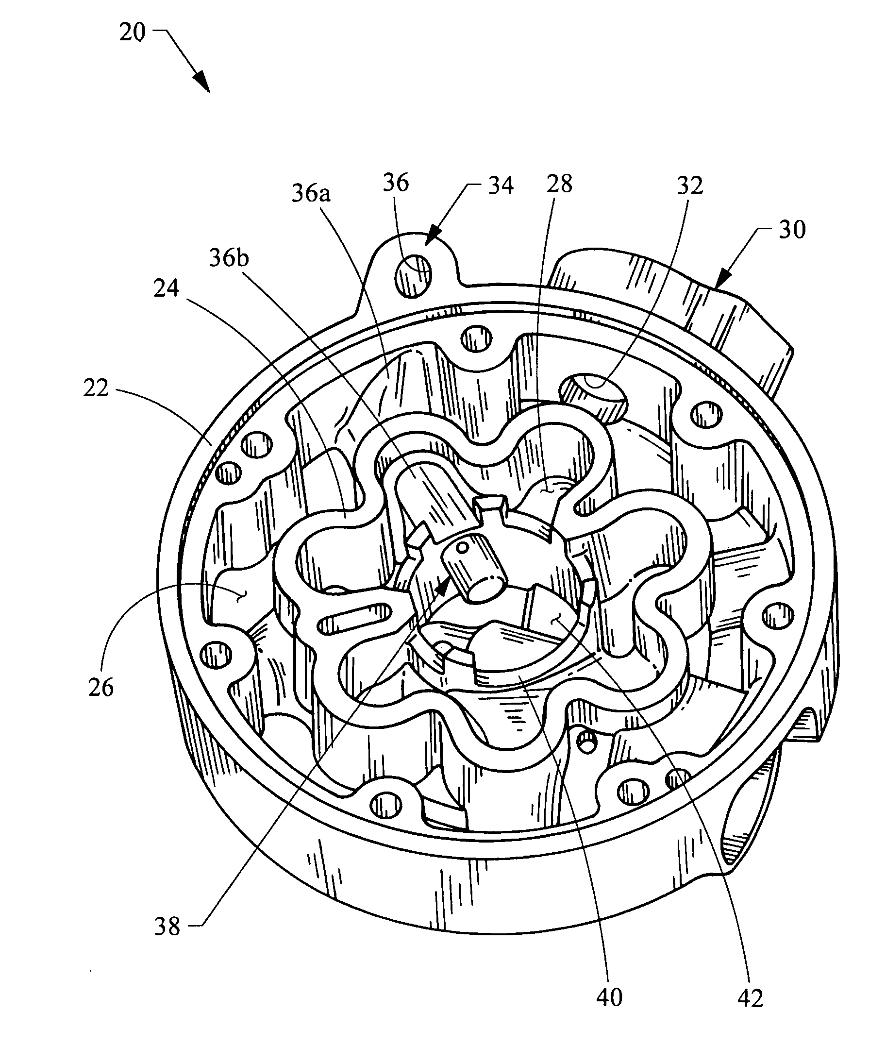
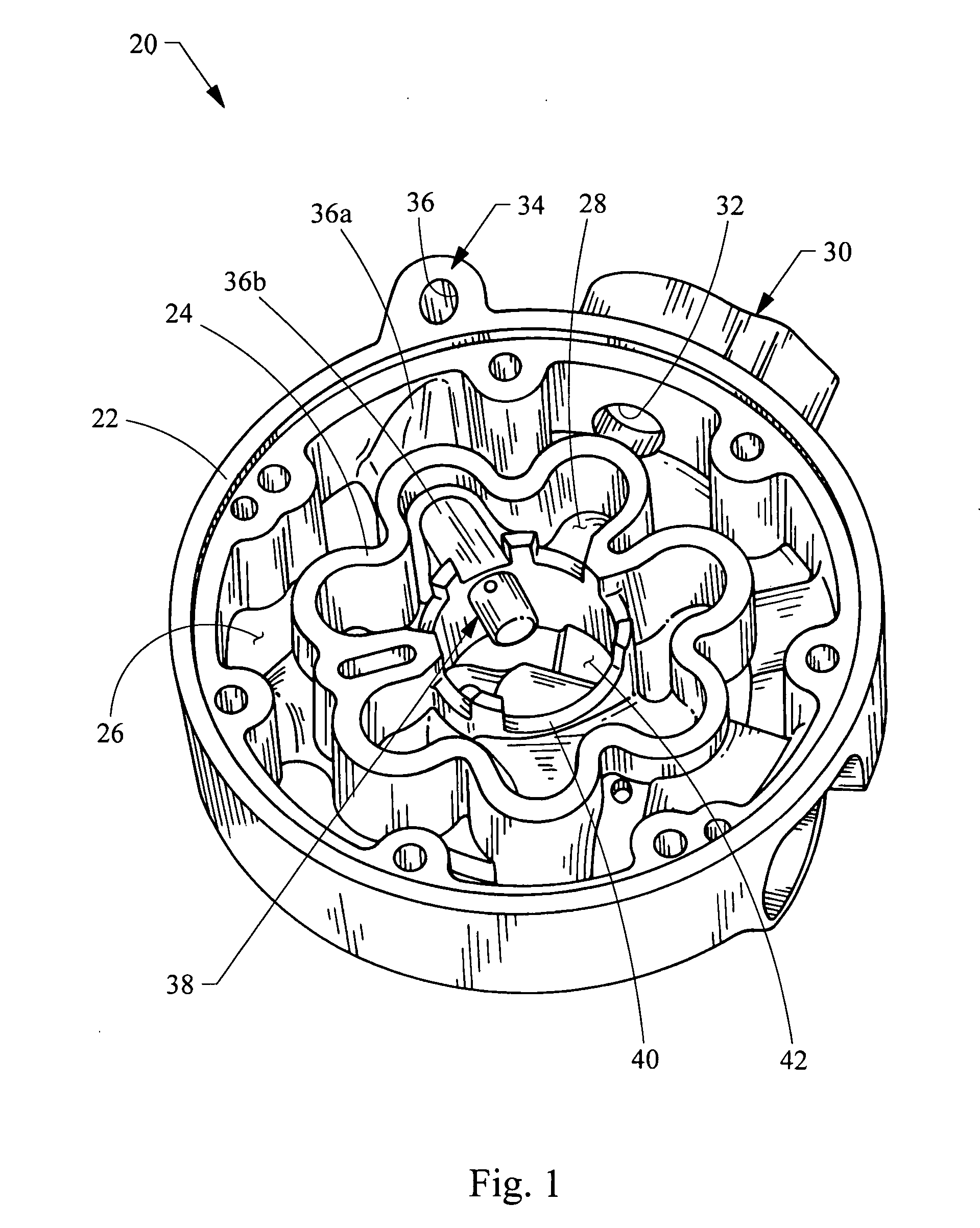
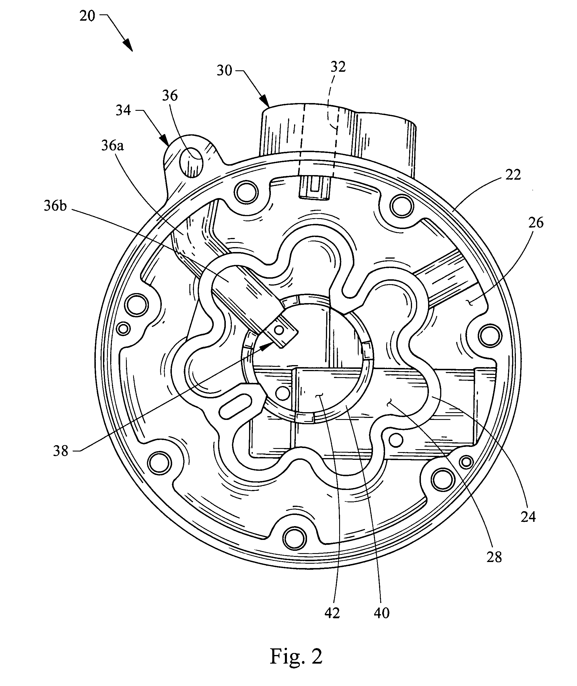
[0015] Turning now to the figures, FIGS. 1 and 2 illustrate a rear housing 20 that is designed for reducing the pressure pulsations and NVH in a compressor (not shown). A compressor for an automotive HVAC typically includes a cylinder block receiving lower pressure fluid from the rear housing 20 and providing higher pressure fluid back to the rear housing 20 through the reciprocating movement of pistons within the cylinder block. The rear housing 20 is in communication with the cylinder block in order to route the flow of higher and lower pressure fluid to and from the compressor. The rear housing 20 generally includes an outer wall 22 and an inner wall 24 positioned inside the outer wall 22. Both the inner and outer walls 22, 24 are annular in shape. As used herein, “annular” refers to a ring-shaped structure (i.e. having no particular beginning or end), although not necessarily circular. For example, the inner wall 24 has a flower-shape defined by a series of “petals” which corres...


PUM


Abstract

A rear housing for a compressor reduces NVH without increasing the overall size of the compressor or inducing flow loss. Generally, the compressor includes a cylinder block receiving lower pressure fluid from the rear housing and providing higher pressure fluid back to the rear housing. The rear housing includes an annular outer wall and an annular inner wall defining a suction chamber and a discharge chamber. An inlet is in fluid communication with the suction chamber. An outlet is in fluid communication with the discharge chamber. The outlet includes a discharge passageway having a tubular member projecting into the discharge chamber. The tubular member is defined by a side wall and a closed end wall. The side wall includes a plurality of holes fluidically connecting the discharge chamber and the discharge passageway.

Description

FIELD OF THE INVENTION [0001] The present invention relates generally to compressors and pumps, and more particularly relates to reducing fluid pulsations, noise, vibration and harshness from such compressors and pumps. BACKGROUND OF THE INVENTION [0002] Existing compressors, such as air conditioning compressors found in vehicles, are relatively noisy. In normal use, a fluid such as a refrigerant gas enters the compressor via a suction chamber in the rear housing of the compressor. The fluid then proceeds through the cylinder block and its chambers where it is drawn into and exited by reciprocating piston movement, which compresses the fluid and discharges it out of the pump. The discharge fluid exits the compressor via a discharge chamber also located in the rear housing and positioned adjacent the suction chamber. Compression of the fluid via the series of reciprocating pistons results in large pressure pulsations and fluctuations, which in turn result in the generation of noise, ...

Claims


Application Information

Patent Timeline
IPC IPC(8): F04B53/10
CPCF04B53/001
Inventor BHATIA, KANWALCALLAHAN, RODNEY JAMESSHASKA, KASTRIOT
Owner HANON SYST
Why Eureka
Try Eureka