
Power-branched transmission having a plurality of transmission ratio ranges with continuously variable transmission ratio

a technology of transmission ratio and transmission range, which is applied in the direction of mechanical equipment, transportation and packaging, and gearing, etc., can solve the problems of limited torque transmission capacity, limited transmission ratio variation range, and relatively complicated implementation of reverse gear, so as to prevent overtaking and reliable disengagement of the clutch

Inactive Publication Date: 2007-01-25
LUK LAMELLEN & KUPPLUNGSBAU BETEILIGUNGS KG
View PDF8 Cites 60 Cited by
  • Summary
  • Abstract
  • Description
  • Claims
  • Application Information

AI Technical Summary

Benefits of technology

[0012] In addition, a shift system for a power-branched transmission having a plurality of transmission ratios is provided that ensures short shift paths. Furthermore, a freewheel state is provided which, in combination with suitable operation of the variable speed drive, enables jerk-free shifting. Finally, a variable speed drive clutch unit is provided that can be integrated compactly into a variable speed drive unit.
[0032] The frictional surface provided on the variable speed drive is preferably introduced into a recess in the fixed disk of the variable speed drive. That permits an especially space-saving arrangement. The relatively severe bending of the variable speed drive shaft and the accompanying locally uneven loading of the clutch linings are accepted in that arrangement of the clutch. One side of the clutch is intentionally connected very rigidly with the variable speed drive, in particular with the fixed disk.

Problems solved by technology

One problem with such variable speed drives is their limited transmission ratio variation range and their limited torque transmitting capacity.
On the other hand, it is relatively complicated to implement a reverse gear, so that an additional shaft is usually necessary to reverse the direction of rotation at the output side.

Method used


Image

  • Power-branched transmission having a plurality of transmission ratio ranges with continuously variable transmission ratio
  • Power-branched transmission having a plurality of transmission ratio ranges with continuously variable transmission ratio
  • Power-branched transmission having a plurality of transmission ratio ranges with continuously variable transmission ratio

Examples


Embodiment Construction

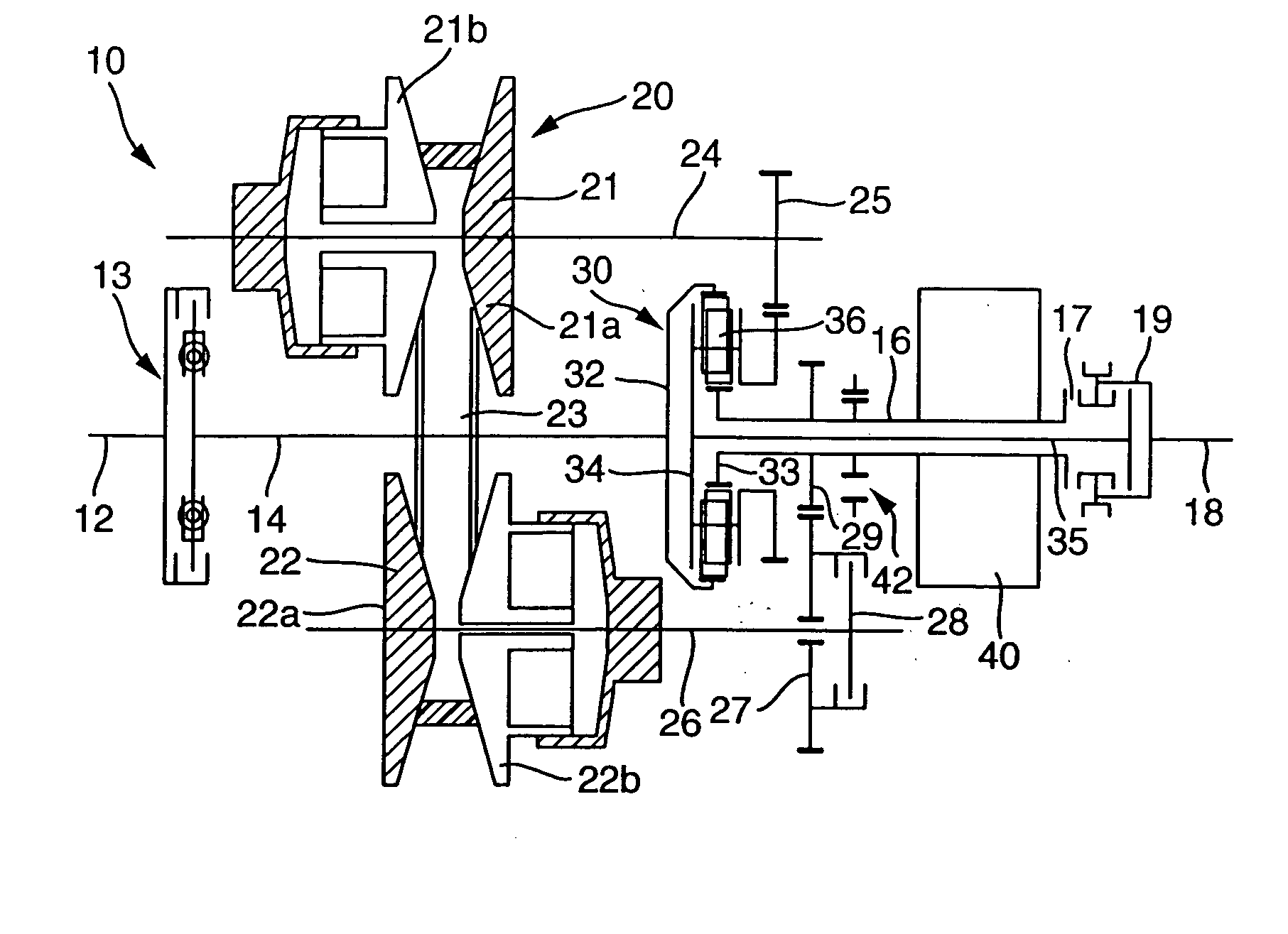
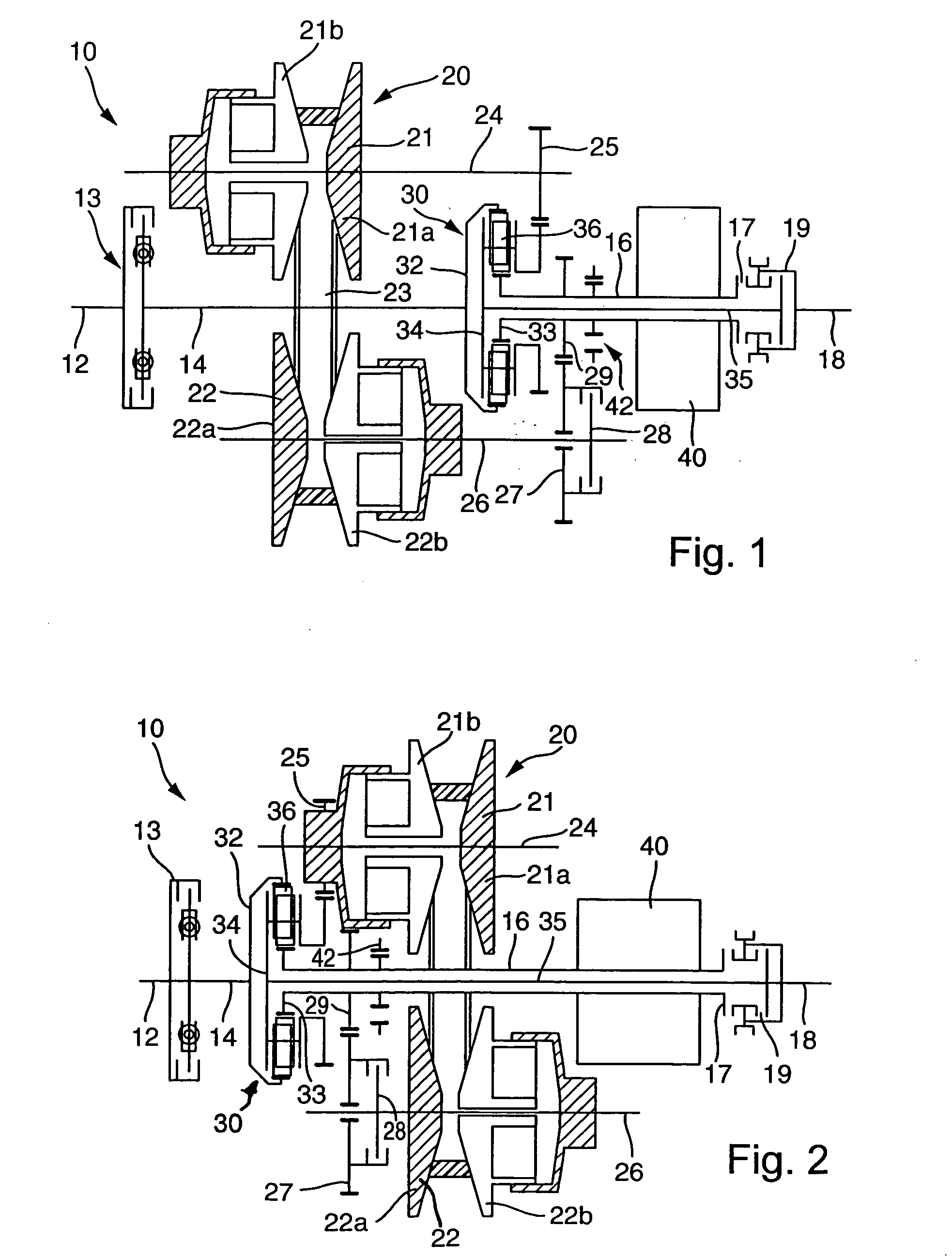
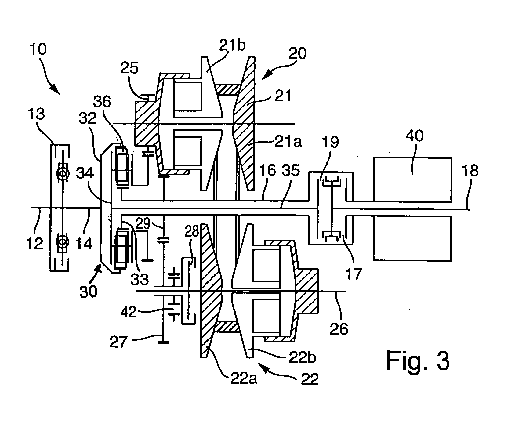
[0053]FIG. 1 shows a first embodiment of a power-branched transmission having a plurality of transmission ratio ranges, in particular two operating regions, with a continuously variable transmission ratio. In particular, power-branched transmission 10 has a variable speed drive unit 20, a planetary gear train 30, which is executed as a reversing planetary gear train, as well as an e-machine (electrical machine) 40. Starting for example from an internal combustion engine (not shown) of a motor vehicle, torque can be transmitted via an engine output shaft 12 to a drive shaft 14 of the transmission when clutch 13 between engine output shaft 12 and drive shaft 14 is engaged. In addition, drive shaft 14 is connected to internal ring gear 32 of planetary gear train 30 with a rotationally fixed connection. Sun gear 33 of planetary gear train 30 is connected with a rotationally fixed connection to a hollow shaft 16, which can be connected with a rotationally fixed connection to output shaft...


PUM


Abstract

A power-branched transmission having a plurality of transmission ratio ranges and having a continuously variable transmission ratio. The transmission includes at least one drive shaft operatively connected to an engine with a rotationally fixed connection, a power divider, a variable speed drive, and an output shaft. The power divider is a planetary gear train and the drive shaft is directly coupled with the internal ring gear of the planetary gear train. Also disclosed is a shift system for such a transmission and a variable speed drive unit clutch arrangement.

Description

BACKGROUND OF THE INVENTION [0001] 1. Field of the Invention [0002] The present invention relates to a power-branched transmission having a plurality of transmission ratio ranges and a continuously variable transmission ratio. [0003] 2. Description of the Related Art [0004] Automatic transmissions having a continuously variable transmission ratio are gaining in interest due to the higher driving comfort and convenience, and particularly because of lower fuel consumption as compared with conventional stepped automatic transmissions in motor vehicles that operate with planetary gear trains. Such continuously variable transmissions typically contain a variator, or variable speed drive, which is formed by two parallel pairs of spaced conical disks around which an endless torque-transmitting means passes, and wherein the spacing between the conical disks of the respective conical disk pairs is variable in opposite directions to change the transmission ratio. [0005] One problem with such ...

Claims


Application Information

Patent Timeline
IPC IPC(8): F16H3/72F16H37/02B60K6/445B60K6/543
CPCB60K6/445B60K6/543F16H37/084Y02T10/6247F16H2037/0873Y02T10/6239F16H37/0846Y02T10/62F16H9/26F16H9/00
Inventor TENBERGE, PETER
Owner LUK LAMELLEN & KUPPLUNGSBAU BETEILIGUNGS KG
Learn More