Portable runners starting block

Inactive Publication Date: 2007-01-25
HELD FRLIN W
View PDF3 Cites 16 Cited by
  • Summary
  • Abstract
  • Description
  • Claims
  • Application Information

AI Technical Summary

Benefits of technology

[0009] Each foot block is easily removed from the tie bar and folded flat so that the t

Problems solved by technology

The earlier blocks with the central rail have the disadvantage of being heavy and too large to fit into a runner's equipment bag.
The more recent portable blocks have the disadvantage of being difficult to po

Method used


Image

  • Portable runners starting block
  • Portable runners starting block
  • Portable runners starting block

Examples


Embodiment Construction

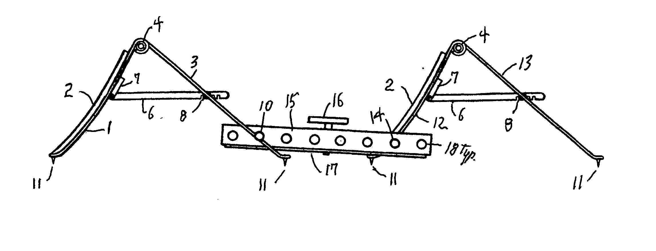
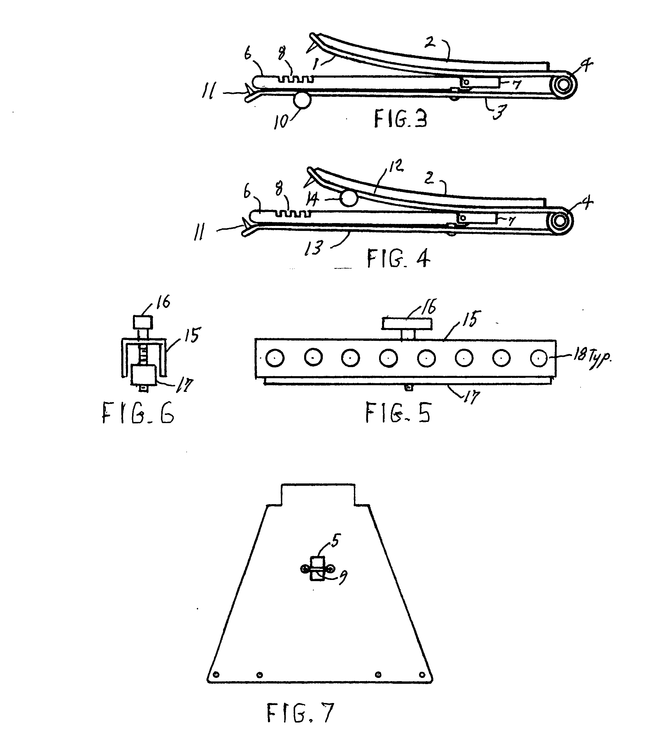
[0017]FIG. 1 shows the profile of the assembled block in a starting configuration. This view shows the brace arms 6 which select and secure the tilt angle of the front plates 1&12. The brace arms are hinged at a dowel pin 7 attached to the front plates 1&12 of each foot block and slide through an opening 5 in the back plates 3&13 (See FIG. 3). The front and back plates are hinged at the top by a hollow pin 4 allowing for angle adjustments and folding flat. Any of the several notches 8 provided in the bottom edge of the brace arm 6 can be dropped over a dowel pin 9 imbedded in each back plate 3&13. Each notch selects a different tilt angle for the foot plate and secures that angle for powerful starts. The spikes 11 are the only part of the assembly that touches the track surface. The front foot block and the back foot block are essentially the same, except for the round rods 10&14 used to connect the foot blocks to the tie bar 15.

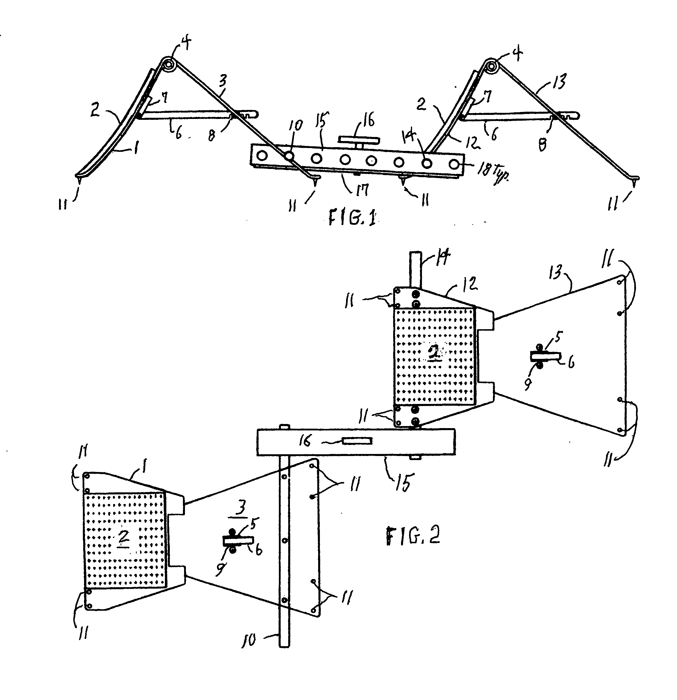
[0018]FIG. 2 is a top view of the assembled block in ...


PUM


Abstract

A lightweight runners starting block assembly with adjustable positions for the foot blocks and adjustable angles for the foot plates is disclosed. The position of the foot blocks can be adjusted by selecting from a series of holes in the central tie bar. The tilt angles of the foot plates can be adjusted by selecting from one of several notches in the brace arms. The foot blocks can be easily removed from the central tie bar and folded flat so that the three parts can be stored in a small bag for convenient portability.

Description

CROSS-REFERENCE TO RELATED APPLICATIONS [0001] Not applicable STATEMENT REGARDING FEDERALLY SPONSORED RESEARCH OR DEVELOPMENT [0002] Not applicable REFERENCE TO SEQUENCE LISTING, A TABLE, OR A COMPUTER PROGRAM LISTING COMPACT DISK APPENDIX [0003] Not applicable BACKGROUND OF THE INVENTION [0004] This invention relates to equipment used by runners to get a good start in a sprint race. Initially starting blocks were developed for dirt tracks with large spikes driven into the dirt to keep them from slipping. Starting blocks generally evolved into assemblies with a central rail and a moveable block attached to each side as in U.S. Pat. No. 3,494,615 by G. L. Moore. With the advent of synthetic track surfaces starting blocks generally used shorter spikes to avoid damaging the track surface and often provided tilt angle adjustments for each foot block as in U.S. Pat. No. 4,611,803 by Newton, Jr. More recently, portable starting blocks small enough and light enough to be conveniently carri...

Claims


Application Information

Patent Timeline
IPC IPC(8): A63K3/02
CPCA63K3/023
Inventor HELD, FRANKLIN W.
Owner HELD FRLIN W
Why Eureka
Try Eureka