
Guidewire apparatus with an expandable portion and methods of use

a technology of guidewires and distal sections, which is applied in the field of guidewires, can solve the problems of entanglement of the tip portion of the catheter device, dangerous condition of deformation and possibly dislodging the stent from the main vessel, and fish-mouthing, so as to improve the ability of the system to cross, and the effect of increasing the combined system pushability

Inactive Publication Date: 2007-01-25
ABBOTT LAB INC
View PDF17 Cites 111 Cited by
  • Summary
  • Abstract
  • Description
  • Claims
  • Application Information

AI Technical Summary

Benefits of technology

[0011] The expandable guidewire apparatus 20 of the present invention may be utilized in place of any conventional guidewire. It is contemplated that the guidewire of the present invention may be particularly useful in aligning and positioning a stent within a body duct. In particular it is contemplated that the present invention may be utilized in combination with a dedicated bifurcation stent system, wherein the bifurcation stent system includes an opening or a portion to be aligned with the side branch vessel. The present invention may be utilized to aid in orientation of the opening or portion with the side branch vessel by providing the user with the ability to apply a rotational force to the distal end of the stent delivery system.
[0012] Alternatively, it is contemplated that the guidewire of the present invention may be useful for transmitting axial loads to a medical device. In particular it is contemplated that the present invention may be utilized in combination with a stent system. The present invention may be utilized to aid in crossing a difficult to cross lesion with the stent system, such as a chronic total occlusion. The present invention provides the user with the ability to increase the combined system pushability thereby improving the ability of the system to cross through a resistant lesion.
[0021] Another aspect of the present invention includes a method for reducing potential flaring between a guidewire and a distal section of a medical device inserted over the guidewire during a medical procedure. The distal section of the medical device includes a working element and defines a guidewire lumen extending through the working element and terminating at a distal opening thereof. The method includes orienting the guidewire, having an elongated main section and an expandable section associated with a distal portion of the main section, in the guidewire lumen such that the expandable section is positioned proximate to the distal opening into the guidewire lumen of the medical device. The method further includes actuating the expandable section of the guidewire apparatus from a base diameter unexpanded state to an expanded state. In the unexpanded state, base diameter is sized and dimensioned for substantially interference free axial and rotational passage through the guidewire lumen. In the expanded state, the expandable section is sized and dimensioned to substantially fill the guidewire lumen opening of the distal section to form a relatively smooth transition ramp. The ramp formed by the expandable section tapers radially outward, from the base diameter of the guidewire to at least substantially transverse cross-sectional dimension of the guidewire lumen opening at the distal section of the medical device.

Problems solved by technology

Another problem associated with conventional guidewires occurs when multiple guidewires are required for a medical procedure.
Occasionally, a tip portion of the catheter device becomes entangled with the stent struts when attempting to access the side branch.
This clearance, however, can cause a phenomenon known as “fish-mouthing”.
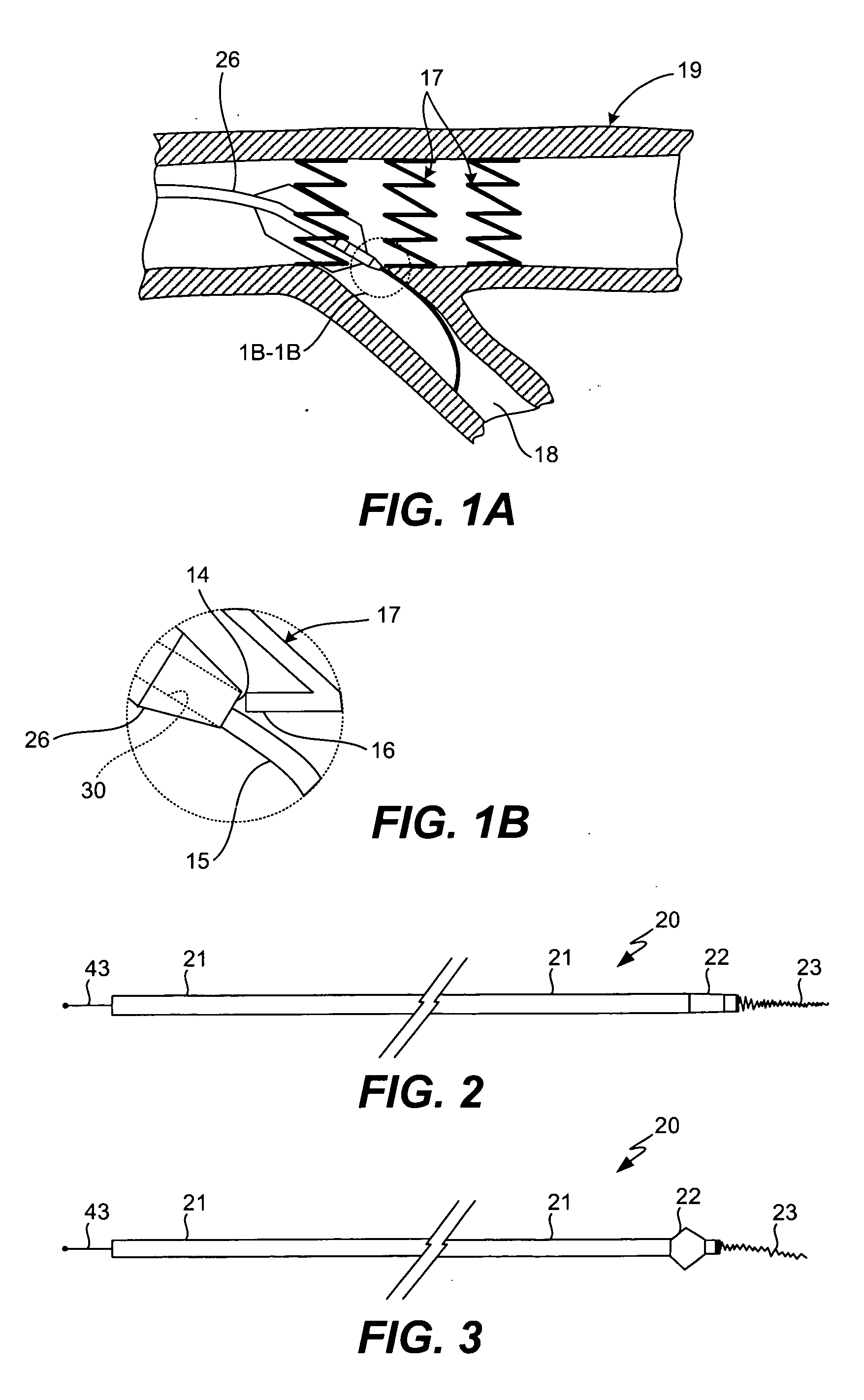
In some cases, however, this flaring can cause difficulties when tracking the catheter device 26 past a difficult obstacle as it can catch on protruding surfaces (e.g. the struts 16 of an expanded stent 17).
Moreover, if the catheter tip becomes tangled on the struts this could lead to a dangerous condition of deforming and possibly dislodging the stent from the main vessel.

Method used


Image

  • Guidewire apparatus with an expandable portion and methods of use
  • Guidewire apparatus with an expandable portion and methods of use
  • Guidewire apparatus with an expandable portion and methods of use

Examples


Embodiment Construction

[0045] While the present invention will be described with reference to a few specific embodiments, the description is illustrative of the invention and is not to be construed as limiting the invention. Various modifications to the present invention can be made to the preferred embodiments by those skilled in the art without departing from the true spirit and scope of the invention as defined by the appended claims. It will be noted here that for a better understanding, like components are designated by like reference numerals throughout the various Figures.

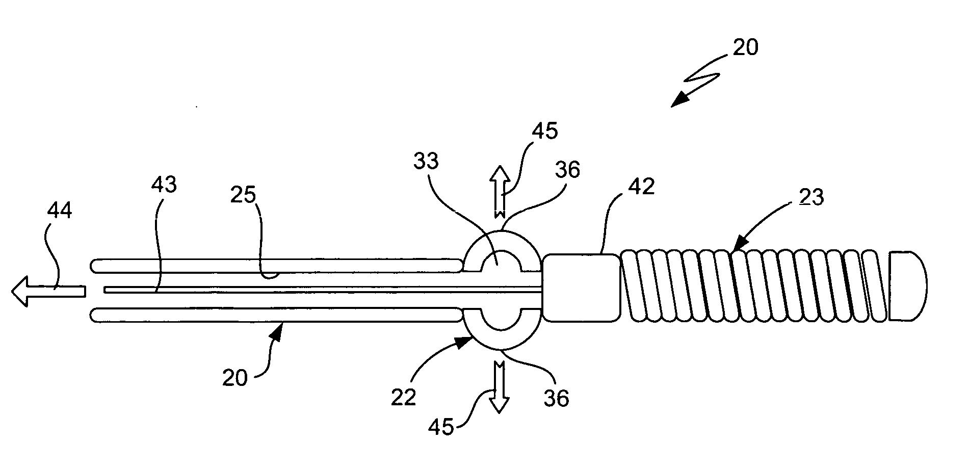
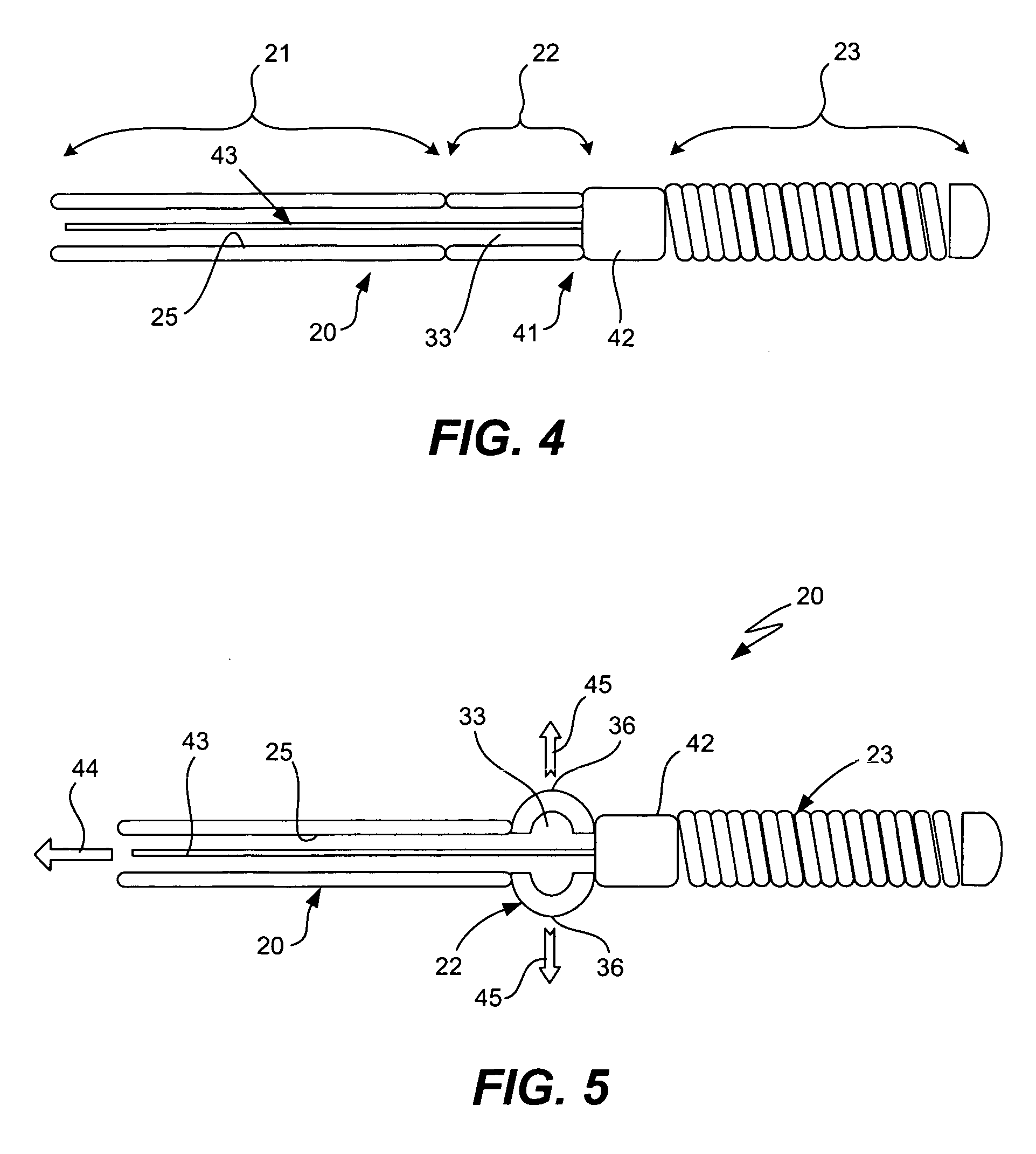
[0046] Referring now to FIGS. 2-5, an expandable guidewire apparatus 20 in accordance with the present invention is shown having an elongated main section 21, an expandable section 22, and a flexible tip section 23. The elongated main section 21 generally forms a substantial portion of the entire length of the guidewire apparatus, and defines an actuating lumen 25 extending substantially the length of the main section to a distal...


PUM


Abstract

A guidewire apparatus for a medical device that includes an expandable guidewire section that can be locked in an expanded state. In one use, the expandable section can be temporarily locked to a working element of a medical device to facilitate the transmission of torque from the guidewire to the medical device. Hence, this configuration may be utilized to aid in orientation of the working element with a vessel side branch by providing the user with the ability to apply a rotational force to the distal end of the stent delivery system. Another use includes docking the expandable section near an opening into a guidewire lumen at the catheter tip. This configuration is particularly useful in forming a smooth transition between the guidewire and the catheter tip to reduce the phenomenon of fish-mouthing.

Description

RELATED APPLICATION DATA [0001] The present application claims priority under 35 U.S.C. §119 to U.S. Provisional Application Ser. No. 60 / 677,950, naming Von Oepen as the inventor, filed May 4, 2005, and entitled EXPANDABLE GUIDEWIRE, and U.S. Provisional Application Ser. No. 60 / 736,638, naming Von Oepen and Yribarren as the inventors, filed Nov. 15, 2005, and entitled GUIDEWIRE HAVING AN EXPANDING PORTION AND METHODS OF USE, both of which are incorporated herein by reference in their entirety and for all purposes.FIELD OF THE INVENTION [0002] The invention generally pertains to guidewires, and more particularly to guidewires having an expandable distal section that can be secured in an expanded condition to facilitate the transmission of torque or axial loads to a medical device through which the guidewire is disposed, and / or reduce entanglement of the medical device with a deployed endoprosthesis device through which it is to pass. BACKGROUND OF THE INVENTION [0003] A wide variety ...

Claims


Application Information

Patent Timeline
Patent Type & Authority Applications(United States)
IPC IPC(8): A61M25/00
CPCA61M25/09A61M2025/09183A61M2025/09175A61M2025/09125
Inventor OEPEN, RANDOLF VONYRIBARREN, TRAVISRIETH, THOMASCOFFEY, LORCANZUCKER, ARIK
Owner ABBOTT LAB INC
Learn More