Method and system for TCP large receive offload

a technology of large tcp and receive offload, applied in the field of processing tcp data, can solve the problems of host cpu not being able to handle the overhead produced by large tcp, slowing down of host cpu, and bottlenecking of host cpu

Inactive Publication Date: 2007-01-25
AVAGO TECH WIRELESS IP SINGAPORE PTE
View PDF4 Cites 32 Cited by
  • Summary
  • Abstract
  • Description
  • Claims
  • Application Information

AI Technical Summary

Problems solved by technology

While TCP offloading may alleviate some of the network-related processing needs of a host CPU, as transmission speeds continue to increase, the host CPU may not be able to handle the overhead produced by large amounts of TCP data communicated between a sender and a receiver in a network connection.
If the host CPU is unable to handle the large overhead produced, the host CPU may become the slowest part or the bottleneck in the connection.

Method used


Image

  • Method and system for TCP large receive offload
  • Method and system for TCP large receive offload
  • Method and system for TCP large receive offload

Examples


Embodiment Construction

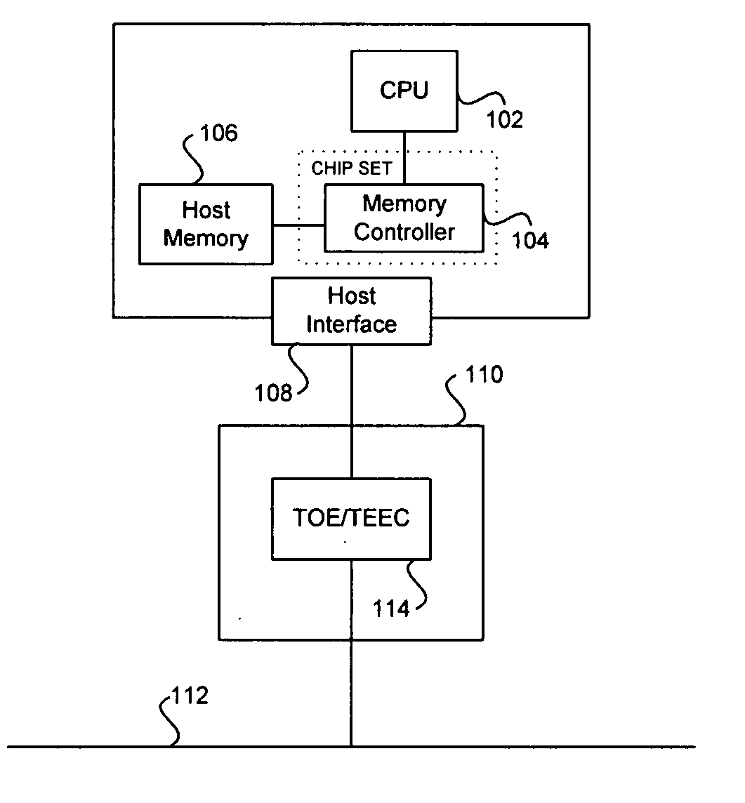
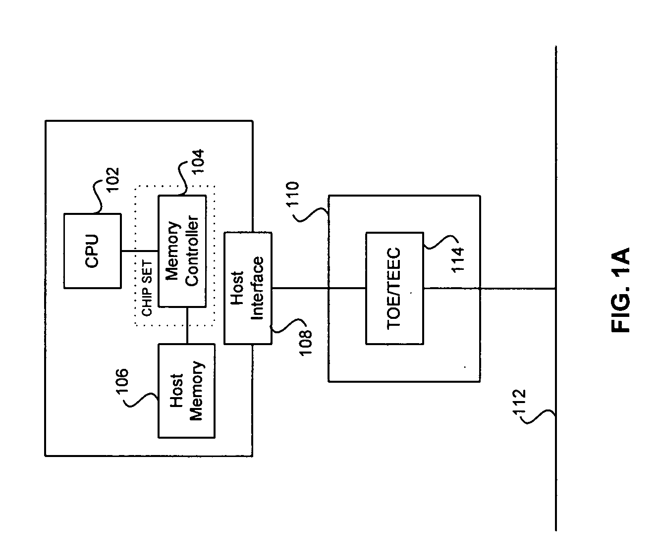
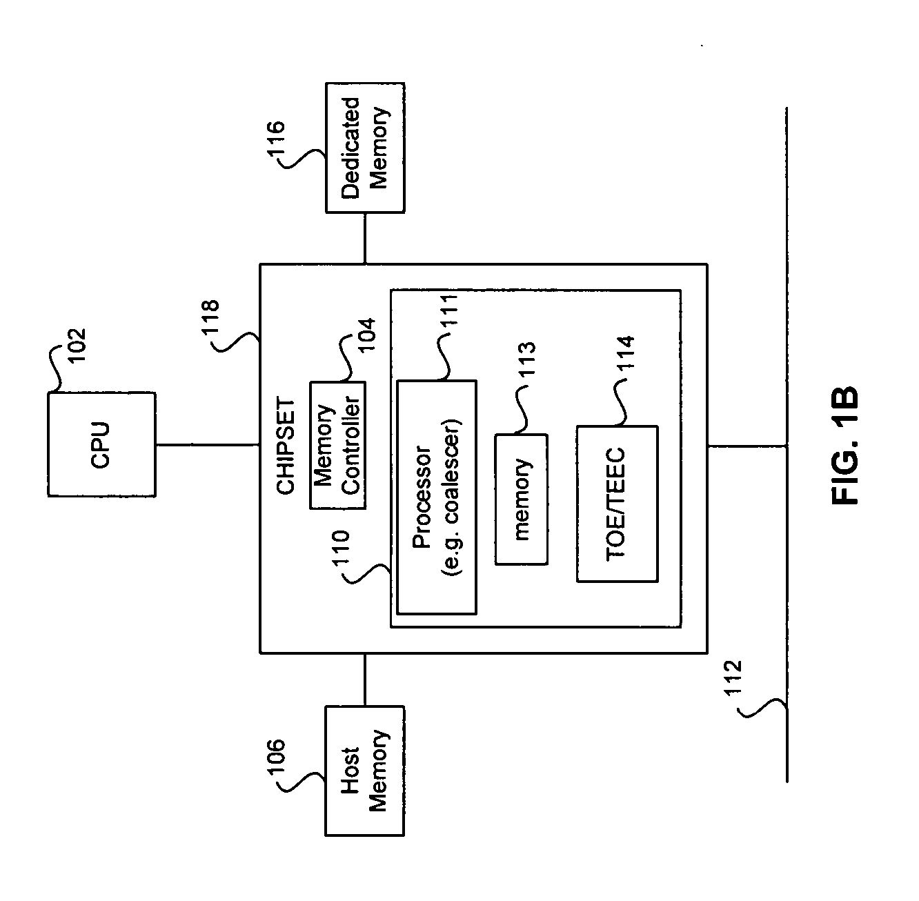
[0024] Certain embodiments of the invention may be found in a method and system for TCP large receive offload (LRO). Aspects of the method and system may comprise a coalescer that may be utilized to collect one or more TCP segments in a network interface card (NIC) without transferring state information to a host system. The collected TCP segments may be temporarily buffered in the coalescer. The coalescer may verify that the network connection associated with the collected TCP segments has an entry in a connection lookup table (CLT). When the CLT is full, the coalescer may close a current entry and assign the network connection to the available entry. The coalescer may update information in the CLT. When an event occurs that terminates the collection of TCP segments, the coalescer may generate a single coalesced TCP segment based on the collected TCP segments. The single coalesced TCP segment, which may comprise a plurality of TCP segments, may be referred to as a large receive seg...


PUM


Abstract

Certain embodiments of the invention may be found in a method and system for transmission control protocol (TCP) large receive offload. A coalescer may be utilized to collect TCP segments in a network interface card (NIC) without transferring state information to a host system. The collected TCP segments may be buffered in the coalescer. The coalescer may verify that the network connection associated with the collected TCP segments has an entry in a connection lookup table (CLT). When the CLT is full, the coalescer may close a current entry and assign the network connection to the available entry. The coalescer may also update information in the CLT. When an event occurs that terminates the collection of TCP segments, the coalescer may generate a single coalesced TCP segment based on the collected TCP segments. The coalesced TCP segment and state information may be communicated to the host system for processing.

Description

CROSS-REFERENCE TO RELATED APPLICATIONS / INCORPORATION BY REFERENCE [0001] This patent application makes reference to, claims priority to and claims benefit from U.S. Provisional Patent Application Ser. No. 60 / 701,723, filed on Jul. 22, 2005. [0002] This application makes reference to: [0003] U.S. Patent Provisional Application Ser. No. 60 / 789,034 (Attorney Docket No. 17003US01), filed on Apr. 4, 2006; [0004] U.S. Patent Provisional Application Ser. No. 60 / 788,396 (Attorney Docket No. 17004US01), filed on Mar. 31, 2006; [0005] U.S. Patent Application Ser. No. 11 / 126,464 (Attorney Docket No. 15774US02), filed on May 11, 2005; [0006] U.S. Patent Application Ser. No. 10 / 652,270 (Attorney Docket No. 15064US02), filed on Aug. 29, 2003; [0007] U.S. Patent Application Ser. No. 10 / 652,267 (Attorney Docket No. 13782US03), filed on Aug. 29, 2003; and [0008] U.S. Patent Application Ser. No. 10 / 652,183 (Attorney Docket No. 13785US02), filed on Aug. 29, 2003.[0009] Each of the above referenced ap...

Claims


Application Information

Patent Timeline
Patent Type & Authority Applications(United States)
IPC IPC(8): G06F15/173
CPCH04L69/16H04L69/12H04L69/166
Inventor FAN, KAN F.
Owner AVAGO TECH WIRELESS IP SINGAPORE PTE
Why Eureka
Try Eureka