Knockdown doorframe for adjustably accommodating wall thickness and building method thereof

a door frame and wall thickness technology, applied in the field of knockdown door frame, can solve the problem of inability to adjust the prior ar

Inactive Publication Date: 2007-02-01
WANG GUO CHI
View PDF18 Cites 29 Cited by
  • Summary
  • Abstract
  • Description
  • Claims
  • Application Information

AI Technical Summary

Benefits of technology

[0005] The object of the present invention is to provide a knockdown doorframe including: a pair or jambs respectively secured to a right and a left vertical side wall of a doorway, each jamb having an adjustable covering plate adjustably shielding a side portion of the jamb with the wall; and a lintel horizontally secured to a top portion of each jamb adjacent to a horizontal top wall of the doorway and having an adjustable horizontal covering plate adjustably shielding an upper portion of the lintel and the horizontal top wall, whereby upon a sliding or telescopic movement of each covering plate in each jamb or lintel, the covering plate may adjustably well shield the jamb or lintel with the wall having variable wall thickness for security and ornamental purposes.

Problems solved by technology

However, such a prior art can not be adjustable for accommodating a wall having variable thickness in many construction sites.

Method used


Image

  • Knockdown doorframe for adjustably accommodating wall thickness and building method thereof
  • Knockdown doorframe for adjustably accommodating wall thickness and building method thereof
  • Knockdown doorframe for adjustably accommodating wall thickness and building method thereof

Examples


Embodiment Construction

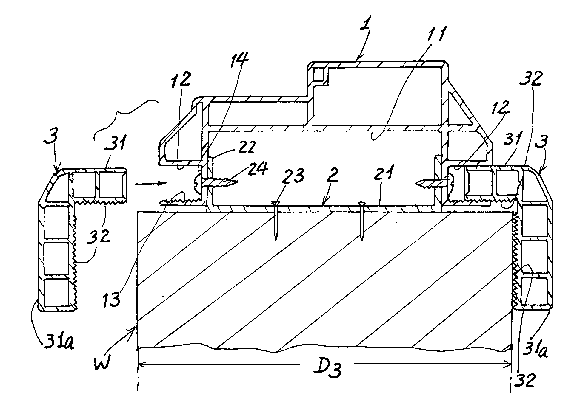
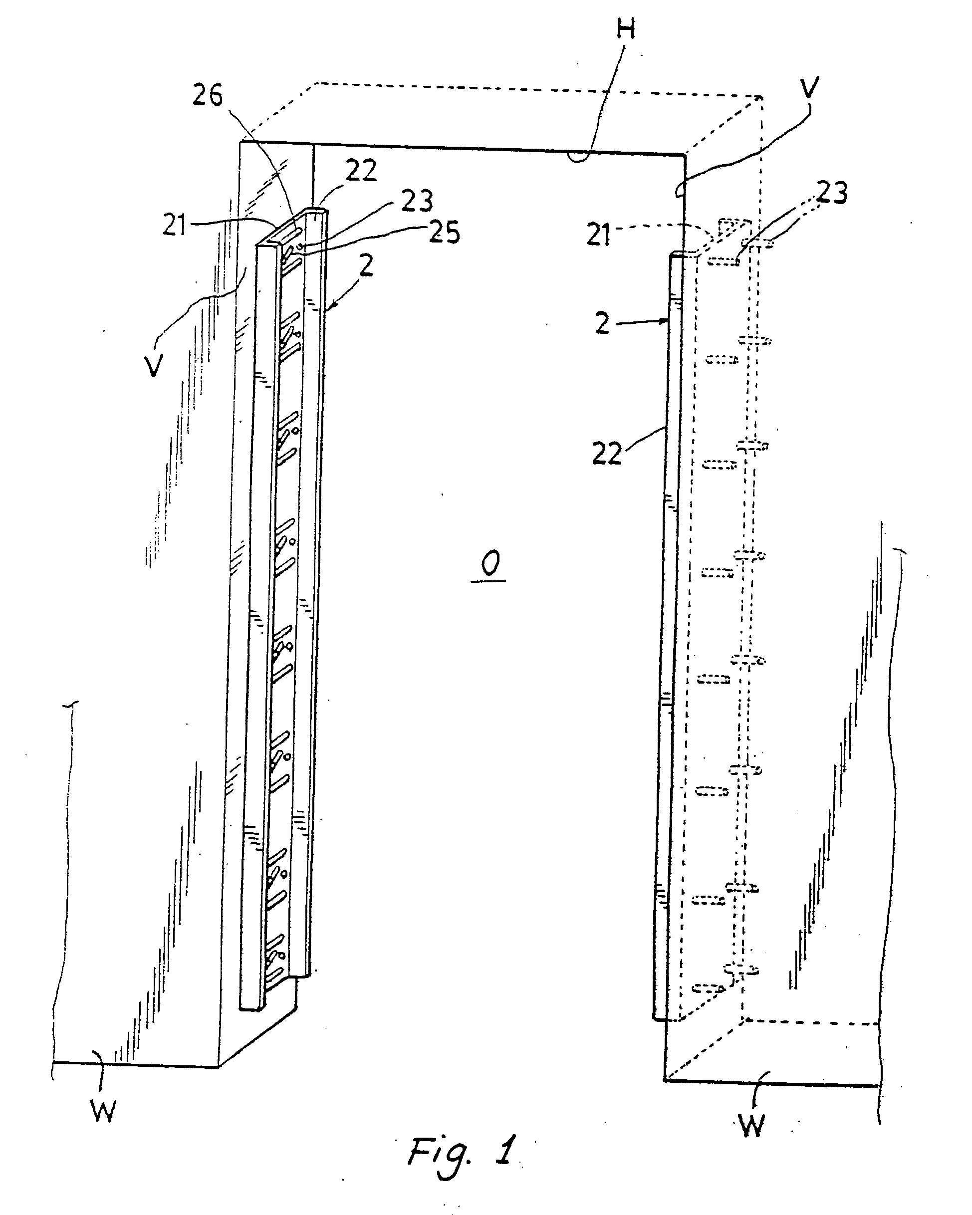
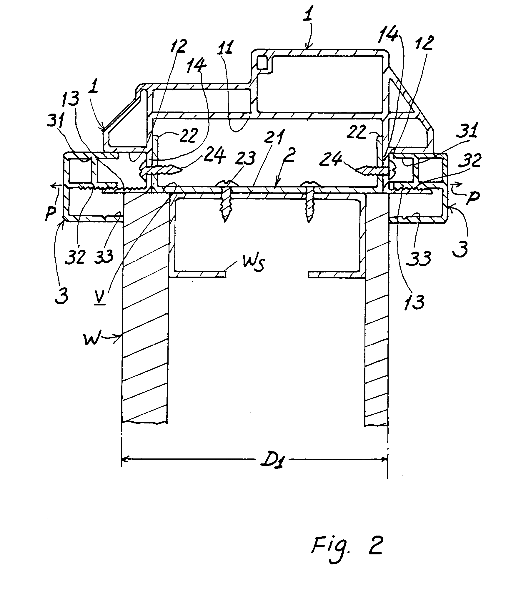
[0014] As shown in FIGS. 2, 1 and 8, the present invention comprises: a pair of jambs I respectively fixed on a left and a right vertical side wall V of a doorway O of a wall W by means of a pair of brackets 2 pre-fixed on the side walls V of the wall W.; and a lintel 4 horizontally fixed on a top portion of each jamb 1 adjacent to a horizontal top wall H of the doorway to form a doorframe.

[0015] Each jamb 1 incorporates a pair of adjustable covering plates 3 for shielding a pair of side portions of the jamb 1 with the wall W for security and ornamental purposes.

[0016] The lintel 4 as horizontally secured between the pair of jambs 1 also incorporates an adjustable horizontal covering plate 3a for shielding an upper portion of the lintel 4 with the horizontal top wall H of the doorway O.

[0017] Each jamb 1 includes: a recess 11 longitudinally recessed in a back portion of the jamb 1 to be engageable with each bracket 2 as pre-fixed on the vertical side wall V of the wall W, two gro...


PUM

PropertyMeasurementUnit
thicknessaaaaaaaaaa
wall thicknessaaaaaaaaaa
widthaaaaaaaaaa

Abstract

A knockdown doorframe includes: a pair or jambs respectively secured to a right and a left vertical side wall of a doorway, each jamb having an adjustable covering plate adjustably shielding a side portion of the jamb with the wall; and a lintel horizontally secured to a top portion of each jamb adjacent to a horizontal top wall of the doorway and having an adjustable horizontal covering plate adjustably shielding an upper portion of the lintel and the horizontal top wall, whereby upon a sliding or telescopic movement of each covering plate in each jamb or in the lintel, the covering plate may adjustably well shield the jamb or lintel with the wall having variable wall thickness for security and ornamental purposes.

Description

BACKGROUND OF THE INVENTION [0001] This application is an improvement based upon the prior art of U.S. Pat. No. 6,192,638 also invented by the same inventor of this application. [0002] Such a prior art of knockdown doorframe includes: a pair of jambs respectively secured on a right and left vertical side wall of a door entrance or doorway by means of brackets longitudinally pre-fixed on the right and left vertical side walls, each jamb having a waterproof pad cushioned on a bottom of the jamb, a lintel horizontally secured on the top portion of each jamb adjacent to a horizontal top wall of the doorway to form an inversed U-shaped doorframe, and each jamb and lintel having a covering plate covered thereon for shielding an aperture between the doorframe and the wall of the doorway for decorative purpose. [0003] However, such a prior art can not be adjustable for accommodating a wall having variable thickness in many construction sites. [0004] The present inventor therefore invented t...

Claims


Application Information

Patent Timeline
Patent Type & Authority Applications(United States)
IPC IPC(8): E04C2/38
CPCE06B1/6061E06B1/30
Inventor WANG, GUO-CHI
Owner WANG GUO CHI
Why Eureka
Try Eureka