MEMS switch actuated by the electrostatic force and piezoelectric force

Inactive Publication Date: 2007-02-01
SAMSUNG ELECTRONICS CO LTD
View PDF2 Cites 43 Cited by
  • Summary
  • Abstract
  • Description
  • Claims
  • Application Information

AI Technical Summary

Benefits of technology

[0010] Accordingly, non-limiting embodiments of the present invention have been made to address the above-mentioned problems, and an aspect of the non-limiting embodiments is to provide a MEMS switch actuated by piezoelectric and electrostatic forces so as to prevent a stiction (i.e., static friction) between contact points.

Problems solved by technology

However, leakage signals may be generated between transmitting and receiving nodes.
Capacities of batteries of compact electronic devices such as portable phones are limited.
However, if the power source is disconnected from the MEMS switch, a stiction (i.e., static friction) occurs between the contact points.
Also, it is difficult to fabricate the contact points having the gap of several μm or less.
As a result, fabricating yield is decreased.

Method used


Image

  • MEMS switch actuated by the electrostatic force and piezoelectric force
  • MEMS switch actuated by the electrostatic force and piezoelectric force
  • MEMS switch actuated by the electrostatic force and piezoelectric force

Examples


Embodiment Construction

[0028] Certain non-limiting embodiments of the present invention will be described in greater detail with reference to the accompanying drawings.

[0029] In the following description, same drawing reference numerals are used for the same elements even in different drawings. The matters defined in the description such as a detailed construction and elements are provided to assist in a comprehensive understanding of the invention. Thus, it is apparent that the present invention can be carried out without those defined matters. Also, well-known functions or constructions are not described in detail since they would obscure the invention in unnecessary detail.

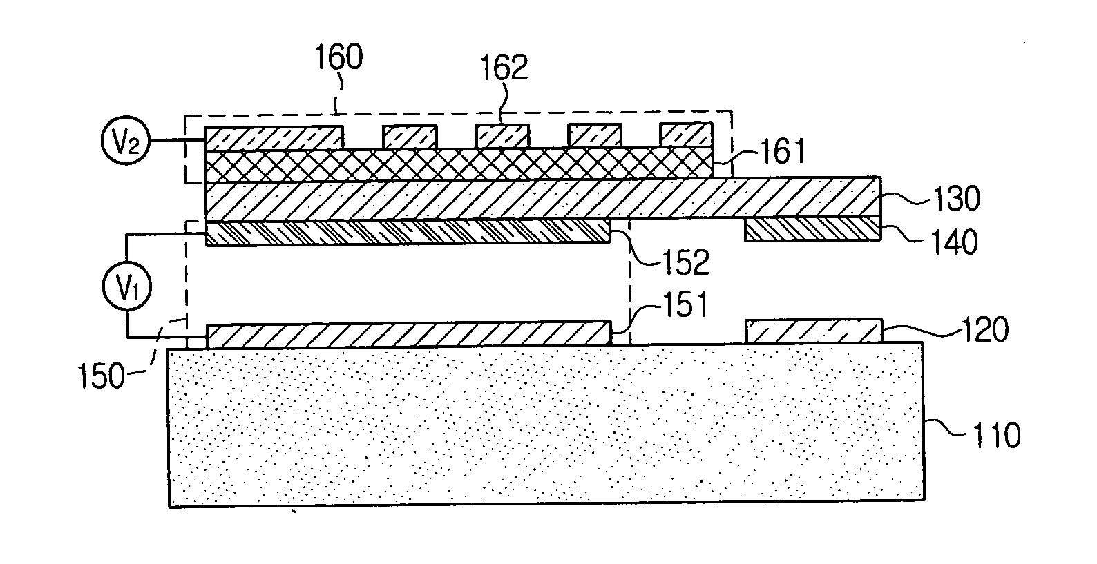
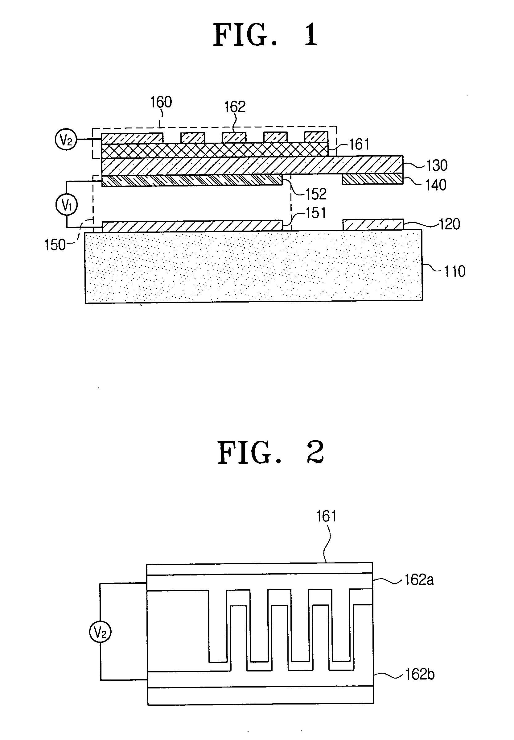
[0030]FIG. 1 is a vertical cross-sectional view of a MEMS switch according to a non-limiting embodiment of the present invention. Referring to FIG. 1, the MEMS switch includes a substrate 110, a first contact point 120, a support layer 130, a second contact point 140, a first actuator 150, and a second actuator 160. The substrate 1...


PUM


Abstract

A MEMS (Micro Electro Mechanical Systems) switch actuated by electrostatic and piezoelectric forces, includes a substrate; a first contact point positioned in a predetermined first area on an upper surface of the substrate; a support layer suspended at a predetermined distance from the upper surface of the substrate; a second contact point formed on a lower surface of the support layer; a first actuator operative to move the support layer in a predetermined direction using an electrostatic force; and a second actuator operative to move the support layer in a predetermined direction using a piezoelectric force. The first actuator is used to turn on the MEMS switch. The second actuator can be used together with the first actuator to turn on the MEMS switch or can be separately used to turn off the MEMS switch. As a result, a stiction can be prevented from occurring between contact points.

Description

CROSS-REFERENCE TO RELATED APPLICATIONS [0001] This application claims priority under 35 U.S.C. § 119(a) from Korean Patent Application No. 2005-68648, filed Jul. 27, 2005 in the Korean Intellectual Property Office, the entire contents of which are incorporated herein by reference. BACKGROUND OF THE INVENTION [0002] 1. Field of the Invention [0003] The present invention relates to a MEMS (Micro Electro Mechanical Systems) switch, and more particularly, to a MEMS switch actuated by piezoelectric and electrostatic forces. [0004] 2. Description of the Related Art [0005] Portable phones have been popularized with the development of the communication industry. Thus, various types of portable phones have been used in every place of the world. Radio frequency (RF) switches are used in portable phones to distinguish signals in different frequency bands. In the prior art, filter type switches are used. However, leakage signals may be generated between transmitting and receiving nodes. Thus, ...

Claims


Application Information

Patent Timeline
IPC IPC(8): H01H51/22
CPCH01H2057/006H01H59/0009H01H1/0036H01H2221/06
Inventor KWON, SANG-WOOKKIM, JUN-OSONG, IN-SANGLEE, SANG-HUNKIM, DONG-KYUNJEONG, HEE-MOONHONG, YOUNG-TACKKIM, JONG-SEOKKIM, CHE-HEUNG
Owner SAMSUNG ELECTRONICS CO LTD
Why Eureka
Try Eureka