
Method of applying a lubricant to a micromechanical device

Inactive Publication Date: 2013-03-21
NAT UNIV OF SINGAPORE
View PDF4 Cites 1 Cited by
  • Summary
  • Abstract
  • Description
  • Claims
  • Application Information

AI Technical Summary

Benefits of technology

[0014]In one embodiment, the lubricant liquid may include a mixture of a lubricant and a solvent. The lubricant liquid may also include further additives that improve the durability of the lubricant eventually applied onto the surface portion of the micromechanical device. Examples of such additives include PFPE (perfluoropolyether)-soluble phosphates [such as phosphazine (X-1P)], PFPE-soluble carboxylic acid and Fomblin DA additives.
[0015]The lubricant may be a chemical substance that lubricates the surface portion of the micromechanical device to prevent stiction. The lubricant may have low surface tension and low contact angle, enabling the lubricant to spread evenly across topographies and providing a hydrophobic property. The lubricant may also have good chemical and thermal stability properties which minimize degradation under use and has high adhesion to the semiconductor substrate via organo-functional bonds. The lubricant may

Problems solved by technology

Due to their small scale, a problem occurs in those surfaces adhere upon contact, due to interactive forces that become significant at the micro scale, rendering the device immoveable and useless.
As a result of these adhesive forces, the surfaces of the components stick to each other either permanently or temporarily, thus resulting in “stiction”.
However, this limits the design and application possibilities of such devices.
However, although this technique may be efficient for modifying large surfaces like top surfaces of MEMS devices, it may not be practical for modifying small surfaces like sidewalls of MEMS devices or surfaces which are difficult to access.
However, vapour deposition usually does not result in good bonding between the lubricant and the surface, thus preventing long term durability of lubricant surface modifications.
Further, the resultant films are also usually too thin to significantly modify the surface properties and avoid the occurrence of “in-use stiction” or “rel

Method used


Image

  • Method of applying a lubricant to a micromechanical device
  • Method of applying a lubricant to a micromechanical device
  • Method of applying a lubricant to a micromechanical device

Examples


Example

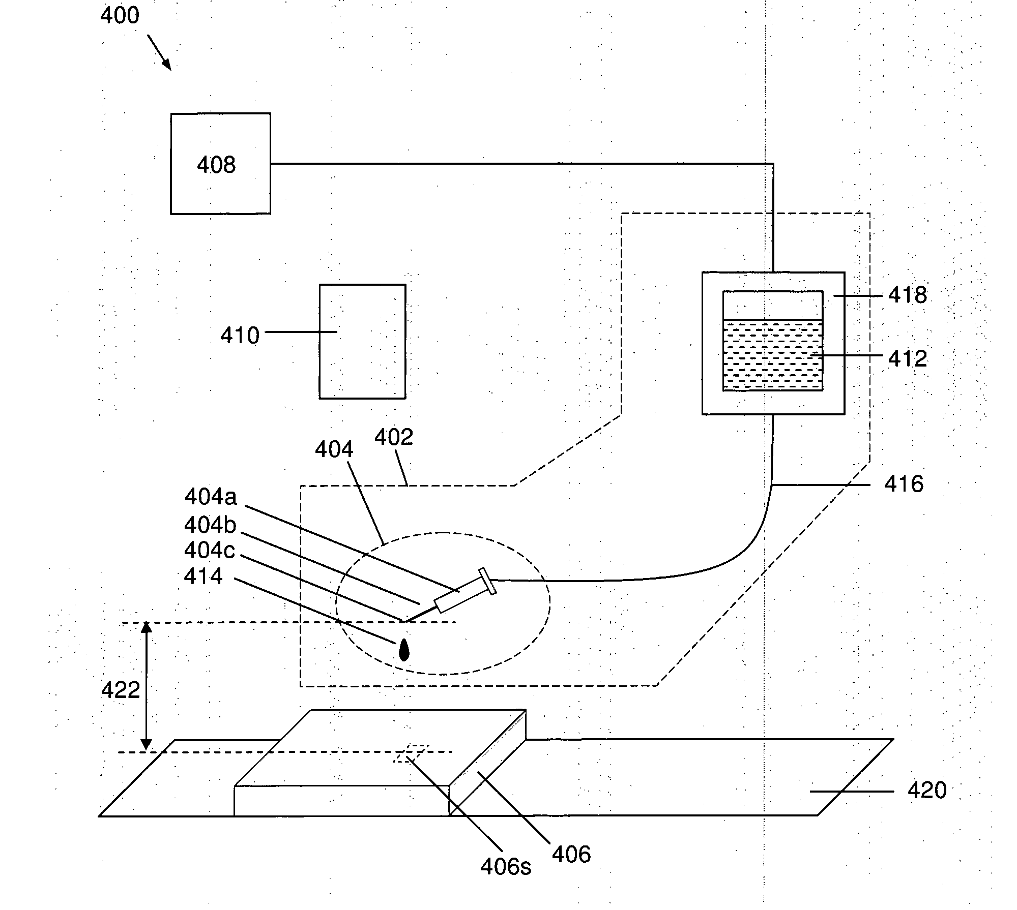
[0077]The following detailed description refers to the accompanying drawings that show, by way of illustration, specific details and embodiments in which the invention may be practiced. These embodiments are described in sufficient detail to enable those skilled in the art to practice the invention. Other embodiments may be utilized and structural, logical, and electrical changes may be made without departing from the scope of the invention. The various embodiments are not necessarily mutually exclusive, as some embodiments can be combined with one or more other embodiments to form new embodiments.

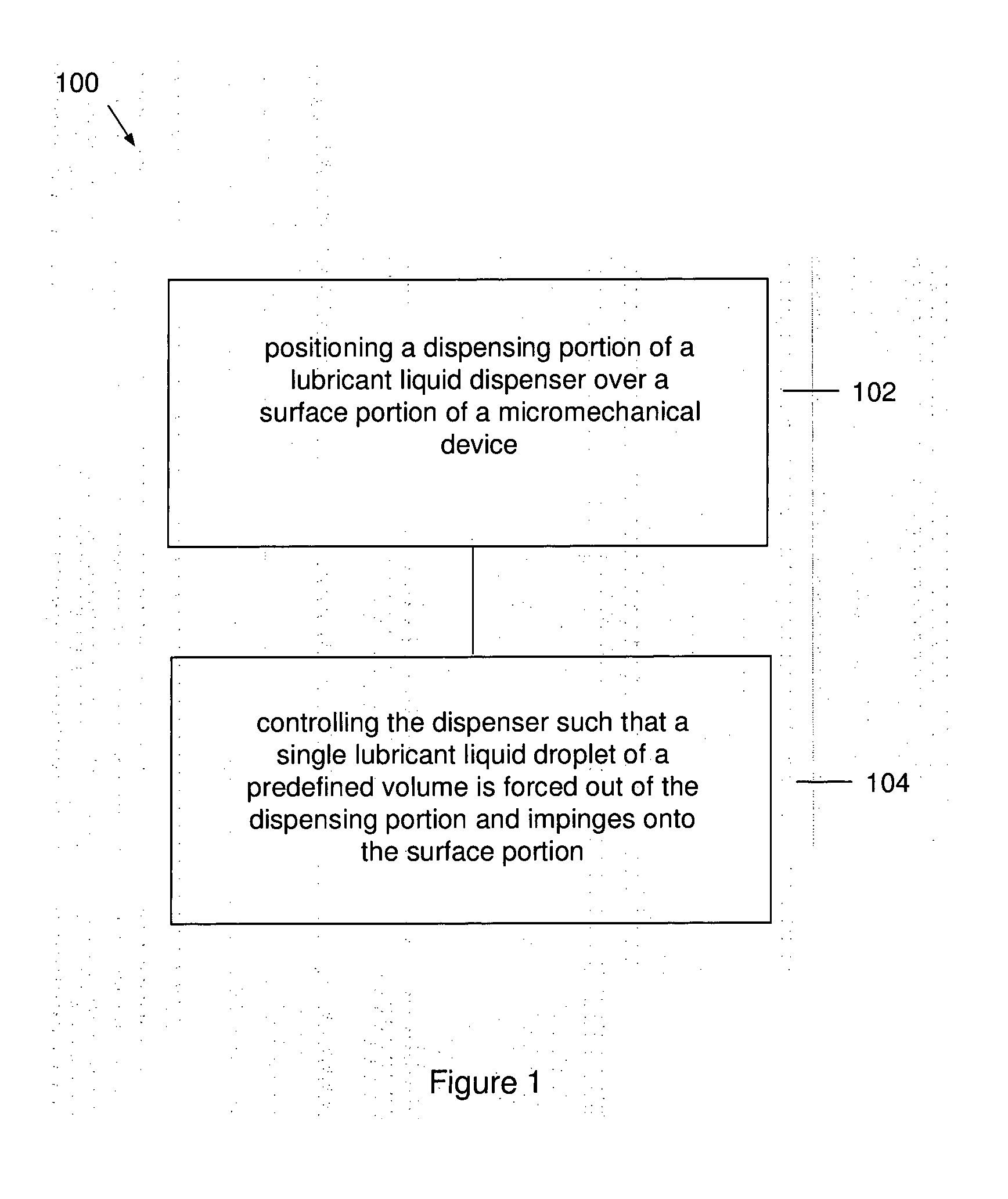
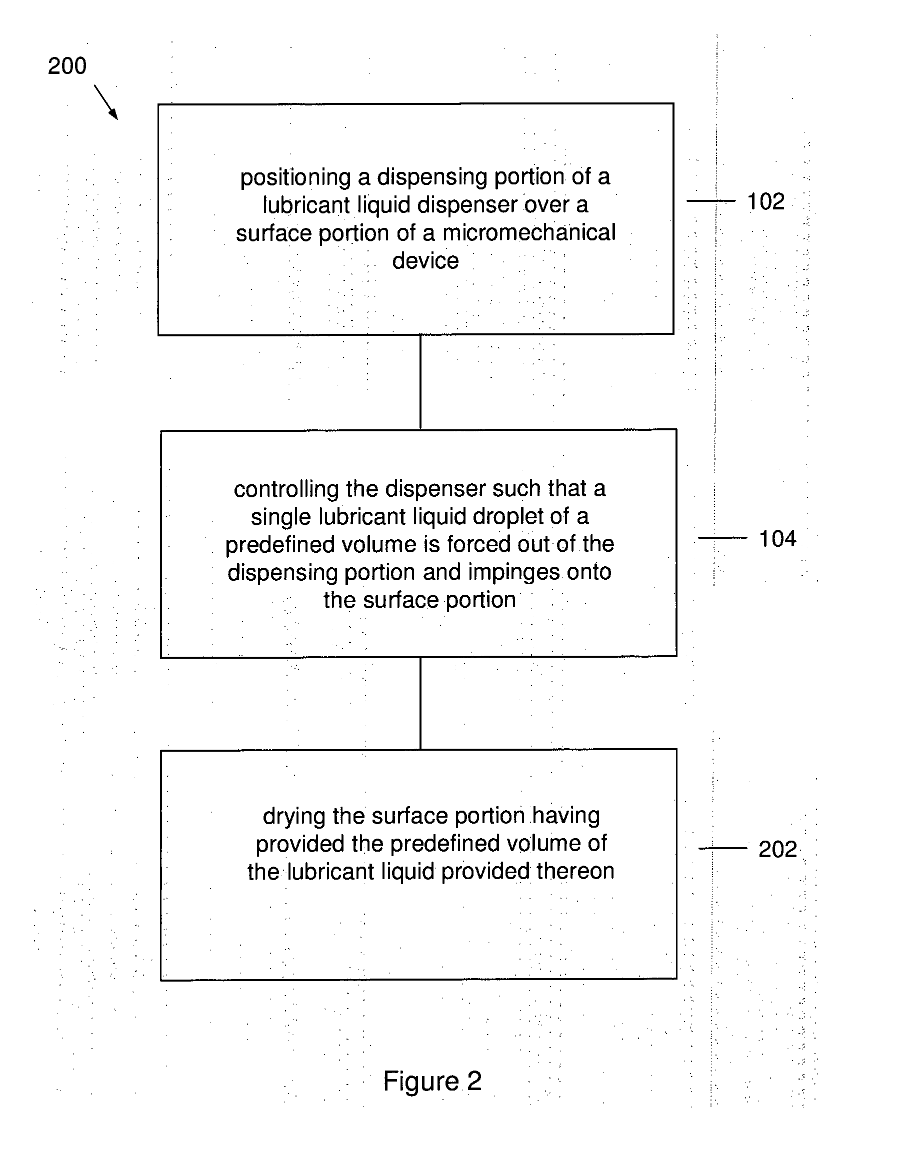
[0078]FIG. 1 shows a flow chart 100 illustrating a method, according to one embodiment of the present invention, of applying a: lubricant to a micromechanical device.

[0079]The method includes two steps, 102 and 104.

[0080]In step 102, a dispensing portion of a lubricant liquid dispenser is positioned over a surface portion of a micromechanical device.

[0081]In step 104, the dispenser is cont...


PUM

PropertyMeasurementUnit
Pressureaaaaaaaaaa
Pressureaaaaaaaaaa
Areaaaaaaaaaaa

Abstract

According to an embodiment of the present invention, a method of applying a lubricant to a micromechanical device is provided. The method includes: positioning a dispensing portion of a lubricant liquid dispenser over a surface portion of a micromechanical device; and controlling the dispenser such that a single lubricant liquid droplet of a predefined volume is forced out of the dispensing portion and impinges onto the surface portion.

Description

FIELD[0001]The invention relates to a method of applying a lubricant to a micromechanical device.BACKGROUND[0002]As the size of a device decreases to micro and nano scales, interactive surface forces between components become critical in Micro-Electro-Mechanical Systems (MEMS) and Nano-Electro-Mechanical Systems (NEMS).[0003]MEMS comprise micron scale fabricated mechanical and electrical components. Due to their small scale, a problem occurs in those surfaces adhere upon contact, due to interactive forces that become significant at the micro scale, rendering the device immoveable and useless. These adhesive forces are known as “stiction”. At the micro-scale, the surface properties that affect the adhesion between surfaces are surface energies, roughness, chemical nature, electrostatic and van der Waals forces, which increase as the size of the devices and components decrease. As a result of these adhesive forces, the surfaces of the components stick to each other either permanently ...

Claims


Application Information

Patent Timeline
IPC IPC(8): B05D5/00B05C5/00C10M107/32
CPCB81B3/0005B81C1/00984B81C2201/0197B81C2201/112Y10T428/24793B05D5/00C10M107/32Y10T428/24802B05C5/00G04D5/00
Inventor SINHA, SUJEET KUMARLEONG, JONATHAN YONGHUINALAM, SATYANARAYANAYU, HONGBINVIJAYAN, HARIKUMARZHOU, GUANGYA
Owner NAT UNIV OF SINGAPORE
Learn More