
Electrostatic actuator, variable capacitance capacitor, electric switch, and method for driving electrostatic actuator

Active Publication Date: 2015-04-30
PIONEER CORP +1
View PDF8 Cites 12 Cited by
  • Summary
  • Abstract
  • Description
  • Claims
  • Application Information

AI Technical Summary

Benefits of technology

The invention relates to a configuration for a device with two electrodes. The device includes a spacer electrode that is connected to one electrode through an insulator, creating a gap between the two electrodes. This gap prevents the accumulation of charges and avoids the phenomenon of stiction. The spacer electrode has the same potential as the one electrode, which ensures that no electric field is generated between the two electrodes. This reduces the likelihood of charge accumulation on the insulator and the spacer electrode, further preventing stiction. The configuration also allows for easy control of potential without changing the potential of the other electrode.

Problems solved by technology

Further, when a voltage is applied between the upper electrode and the lower electrode, a potential difference is caused between the upper electrode and the lower electrode.

Method used


Image

  • Electrostatic actuator, variable capacitance capacitor, electric switch, and method for driving electrostatic actuator
  • Electrostatic actuator, variable capacitance capacitor, electric switch, and method for driving electrostatic actuator
  • Electrostatic actuator, variable capacitance capacitor, electric switch, and method for driving electrostatic actuator

Examples


first embodiment

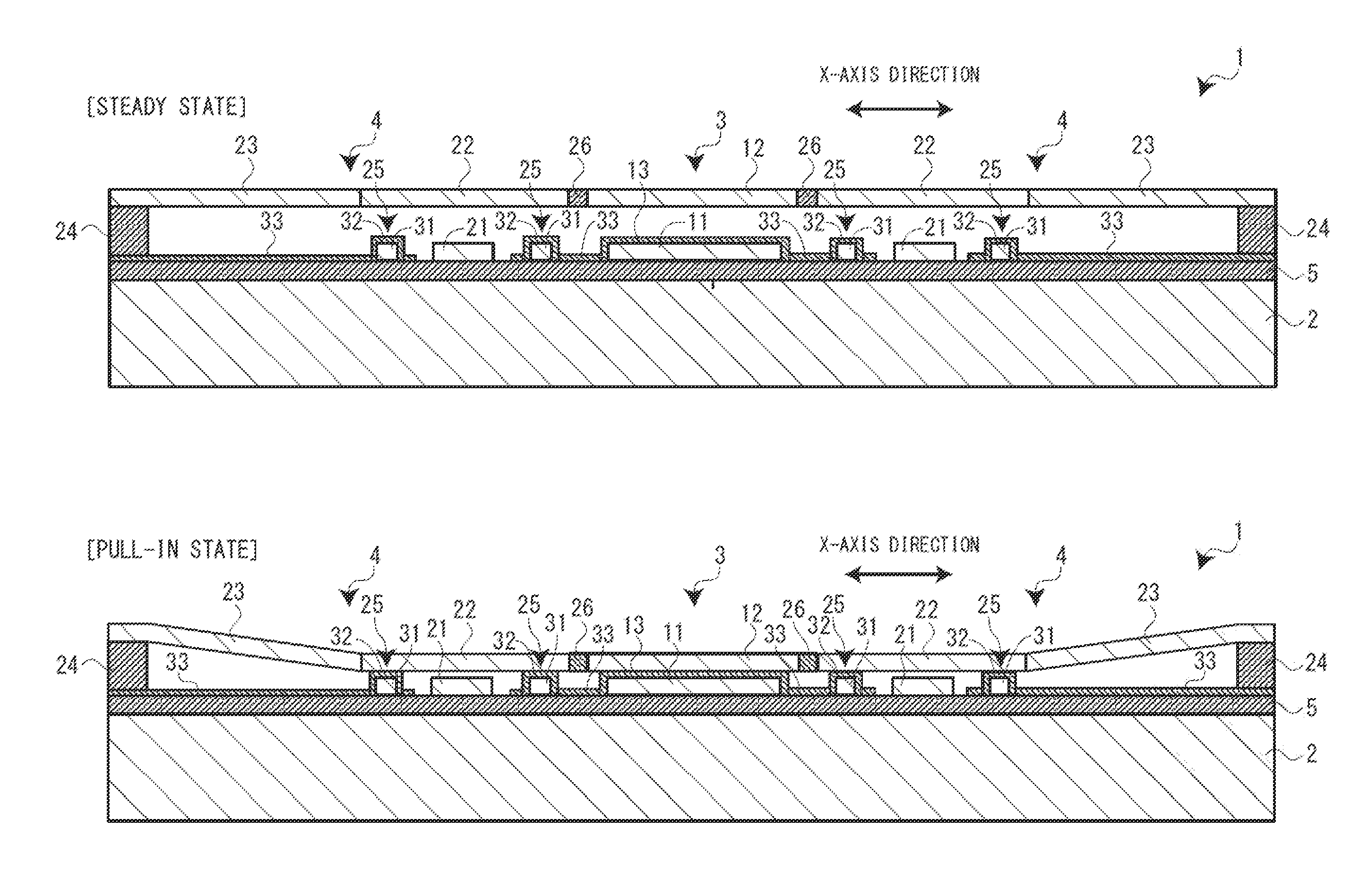
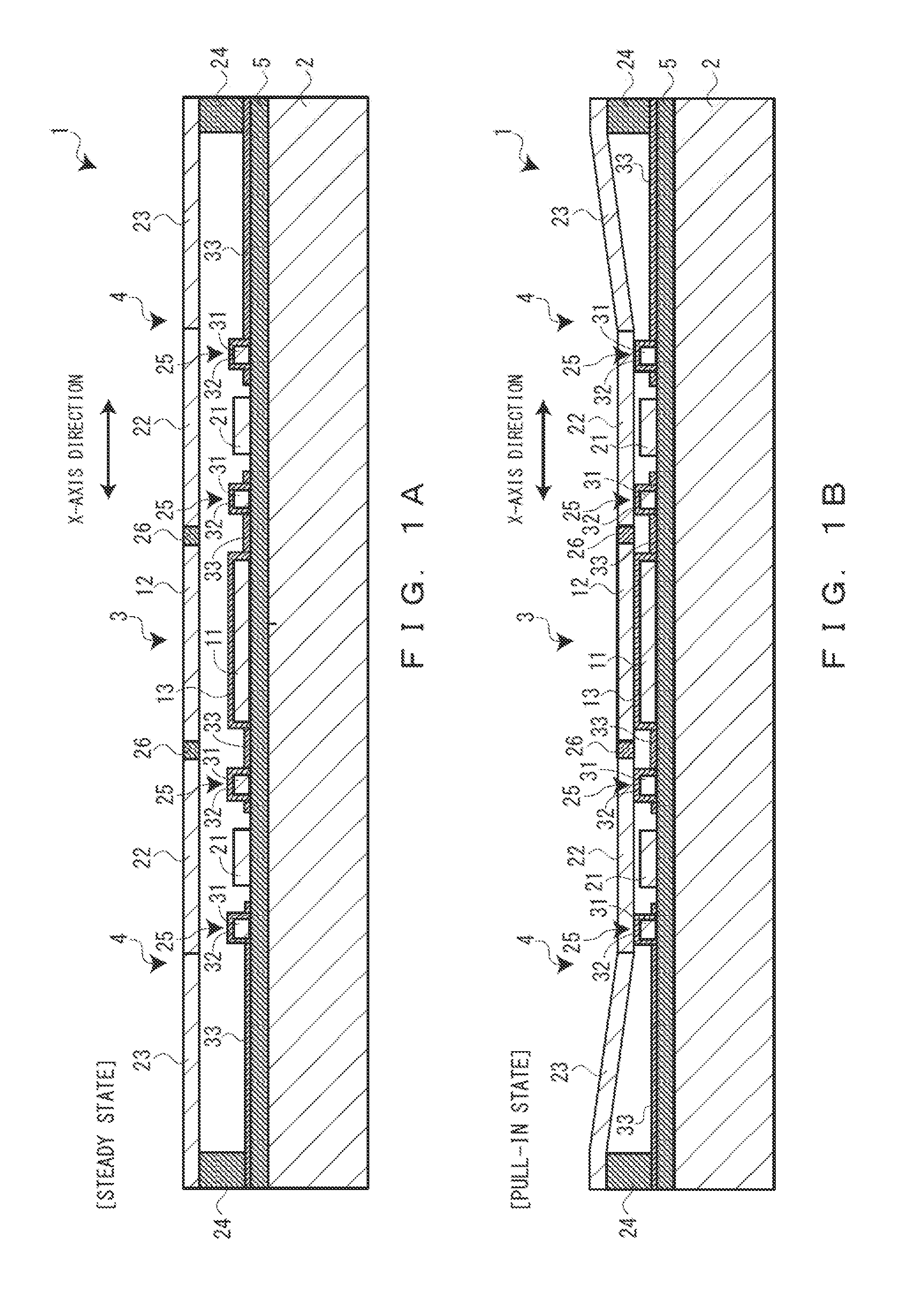
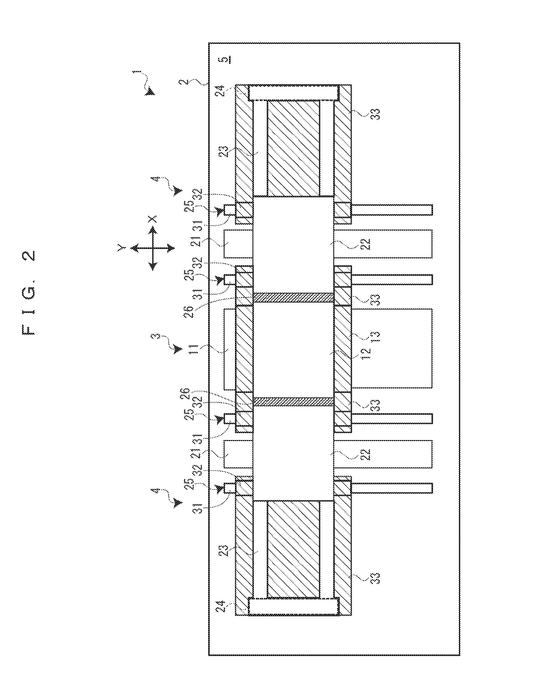
[0030]Hereinafter, a description will be given, with reference to the accompanying drawings, of an electrostatic actuator, a variable capacitance capacitor, and an electric switch according to an embodiment of the present invention. A first embodiment exemplifies a variable capacitance capacitor using electrostatic actuators. The variable capacitance capacitor is a MEMS (Micro Electro Mechanical Systems) device and configured in such a way that an electronic circuit and a mechanical structure are installed on a silicon substrate (semiconductor substrate) using a semiconductor integrated circuit manufacturing technology. Note that the variable capacitance capacitor has a structure to prevent stiction in the electrostatic actuators with spacers and potential control.

[0031]As shown in FIGS. 1A and 1B and FIG. 2, a variable capacitance capacitor 1 has a silicon substrate (substrate) 2, a variable capacitance element 3 that is disposed on the silicon substrate 2, and a pair of electrosta...

second embodiment

[0043]Next, a description will be given of a second embodiment with reference to FIGS. 5A and 5B. The second embodiment exemplifies an electric switch 41 using electrostatic actuators 4. As is the case with the first embodiment, the electric switch 41 is a MEMS device and configured in such a way that an electronic circuit and a mechanical structure are installed on a silicon substrate 2 using a semiconductor integrated circuit manufacturing technology.

[0044]As shown in FIGS. 5A and 5B, the electric switch 41 has the silicon substrate 2, a switch element (switch) 42 that is disposed on the silicon substrate 2, and the pair of electrostatic actuators 4 that is disposed on the silicon substrate 2 and coupled to both sides of the switch element 42. That is, the electric switch 41 switch-drives the switch element 42 using the pair of electrostatic actuators 4 as a driving source. Note that the pair of electrostatic actuators 4 has the same configuration as those of the first embodiment ...


PUM


Abstract

An electrostatic actuator includes: a fixed driving electrode that is disposed on a silicon substrate; a movable driving electrode that is disposed so as to face the fixed driving electrode and approaches the fixed driving electrode with an electrostatic force generated between the movable driving electrode and the fixed driving electrode; and a pair of spacers that comes in contact with the movable driving electrode in an approaching state in which the fixed driving electrode and the movable driving electrode approach each other and forms a prescribed air gap between the fixed driving electrode and the movable driving electrode, wherein each of the spacers has a spacer electrode portion that comes in contact with the movable driving electrode via an insulator and has the same potential as one of the electrodes at least in the approaching state.

Description

TECHNICAL FIELD[0001]The present invention relates to an electrostatic actuator that has a fixed electrode and a movable electrode facing the fixed electrode and causes the movable electrode to approach and separate from the fixed electrode with an electrostatic force, a variable capacitance capacitor, an electric switch, and a method for driving the electrostatic actuator.BACKGROUND ART[0002]A known variable capacitance capacitor has a variable capacitance portion composed of a signal line and an electrode facing the signal line and a pair of actuator portions of a bridge structure in line with both sides of the variable capacitance portion (see Patent Document 1). Each of the actuator portions has a movable-side upper electrode and a fixation-side lower electrode facing the upper electrode. Further, when a voltage is applied between the upper electrode and the lower electrode, a potential difference is caused between the upper electrode and the lower electrode. As a result, an ele...

Claims


Application Information

Patent Timeline
IPC IPC(8): H02N1/00H01H59/00H01G5/16
CPCH02N1/006H01H2059/0072H01H59/00H01G5/16B81B3/001B81B2201/0221
Inventor HANIHARA, KOJI
Owner PIONEER CORP
Learn More