IC tag, IC tag controlling method, and IC tag system

a control method and control method technology, applied in the direction of burglar alarm mechanical actuation, burglar alarm by hand-portable object removal, instruments, etc., can solve the problems of unauthenticated person specifying, leaking personal data associated with the purchaser, and a customer's privacy being violated

Inactive Publication Date: 2007-02-01
NEC ELECTRONICS CORP
View PDF5 Cites 36 Cited by
  • Summary
  • Abstract
  • Description
  • Claims
  • Application Information

AI Technical Summary

Benefits of technology

[0020] According to the present invention, it is possible to provide an IC tag that can be reused after an IC

Problems solved by technology

On the other hand, while attentions are paid to a convenience of RFID, there is a fear that a privacy of a customer is violated.
Further, if a system or user data database stored in the IC tag is searched, personal data associated with the purchaser is specified and leaks.
For example, there is a fear that an unauthenticated person specifies “when” and “what”“who” buys, tracks a purchaser's behavior, and identifies the purchase, and abuses the information.
However, if the IC tag is invalidated in r

Method used


Image

  • IC tag, IC tag controlling method, and IC tag system
  • IC tag, IC tag controlling method, and IC tag system
  • IC tag, IC tag controlling method, and IC tag system

Examples


first embodiment

[0030] First of all, an IC tag system according to a first embodiment of the present invention is described. A feature of the IC tag system of this embodiment is to change a communication protocol based on a KILL command and return the communication protocol to the original one in response to a KILL cancel command.

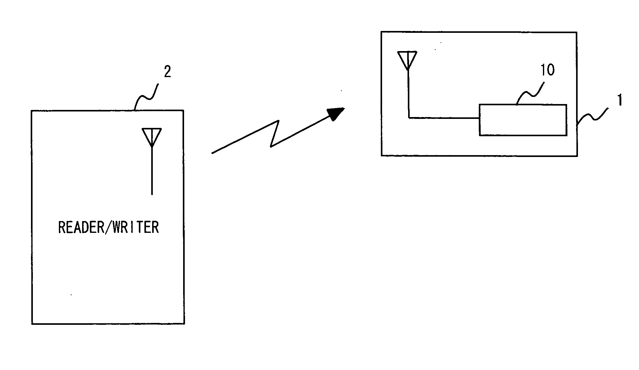
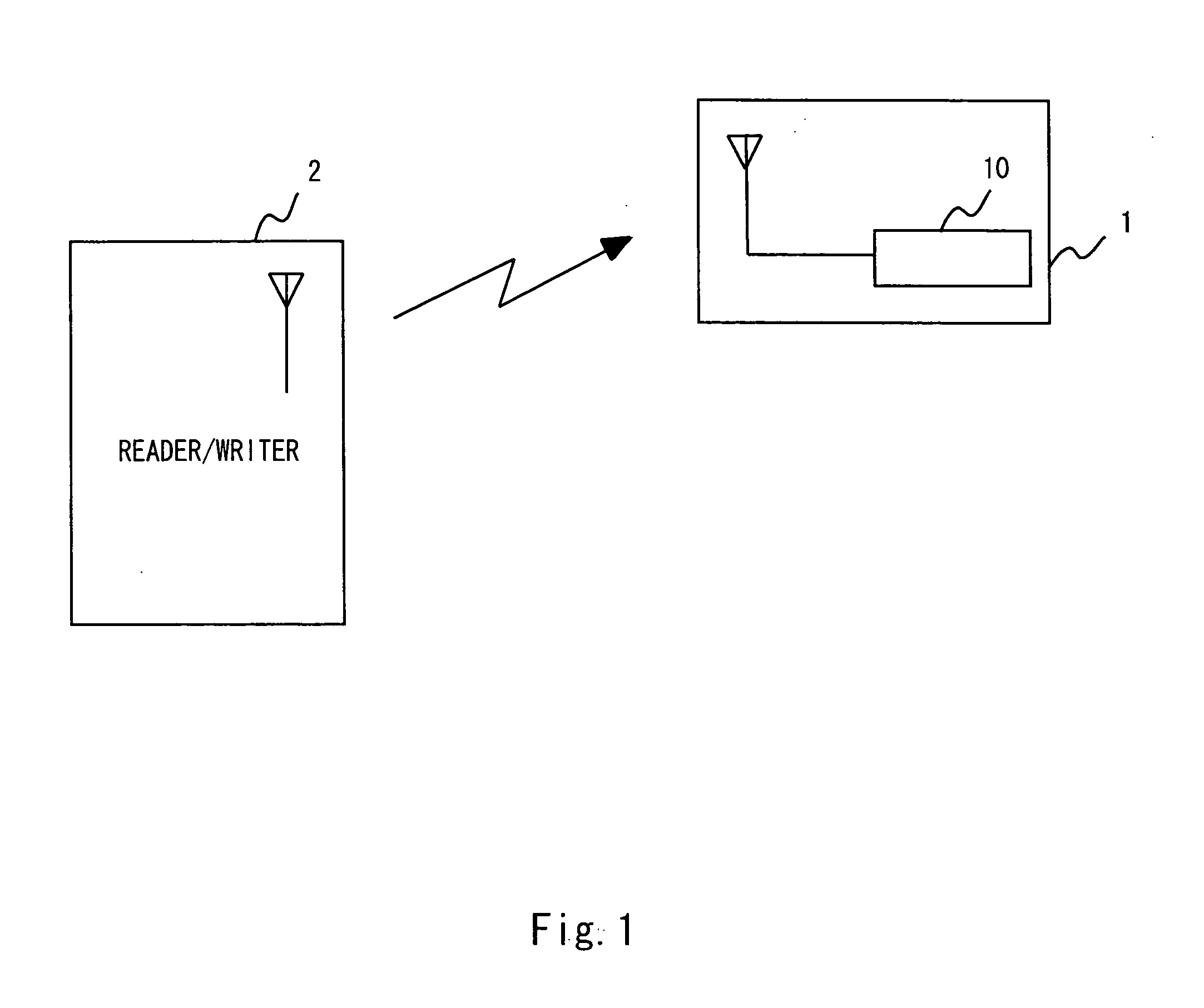
[0031] Referring now to FIG. 1, the configuration of the IC tag system of this embodiment is described. As shown in FIG. 1, the IC tag system includes a IC tag 1 and a reader / writer 2. The IC tag system is a communication system for communicating with the IC tag 1 and the reader / writer 2 by radio based on a predetermined communication protocol.

[0032] The reader / writer 2 is communicably connected with a computer (not shown), and writes / reads predetermined data to / from a storage circuit in the IC tag 1 in response to an instruction from the computer.

[0033] For example, at the time of writing / reading data to / from the IC tag 1, if the reader / writer 2 approaches the IC tag 1...

second embodiment

[0080] Next, an IC tag according to a second embodiment of the present invention is described. A feature of the IC tag of this embodiment is that decoders for analyzing the KILL command, and counters and decoders for analyzing the KILL cancel command are shared. This embodiment describes an example where the counter and decoders are shared as the configuration of the command analyzing unit, but only the counter or decoder is shared. Incidentally, the configuration of the IC tag system or the communication frame of the IC tag of this embodiment is the same as the first embodiment, so its description is omitted here.

[0081]FIG. 6 shows the configuration of a command analyzing unit 151, a command executing unit 152, and a system area 161 of this embodiment. In this embodiment, as compared with the first embodiment ofFIG. 4, neither the 3-bit counter 301 nor the 8-bit decoder 302 is provided, and a bit addition unit 305 is provided instead. Incidentally, the same components as those of ...

third embodiment

[0087] Next, an IC tag according to a third embodiment of the present invention is described. The IC tag of this embodiment has a feature that encoded data is received from the reader / writer in addition to the KILL cancel command to decode the encoded data. Incidentally, the configuration of the IC tag system based on the IC tag of this embodiment is the same as the first embodiment, so its description is omitted here.

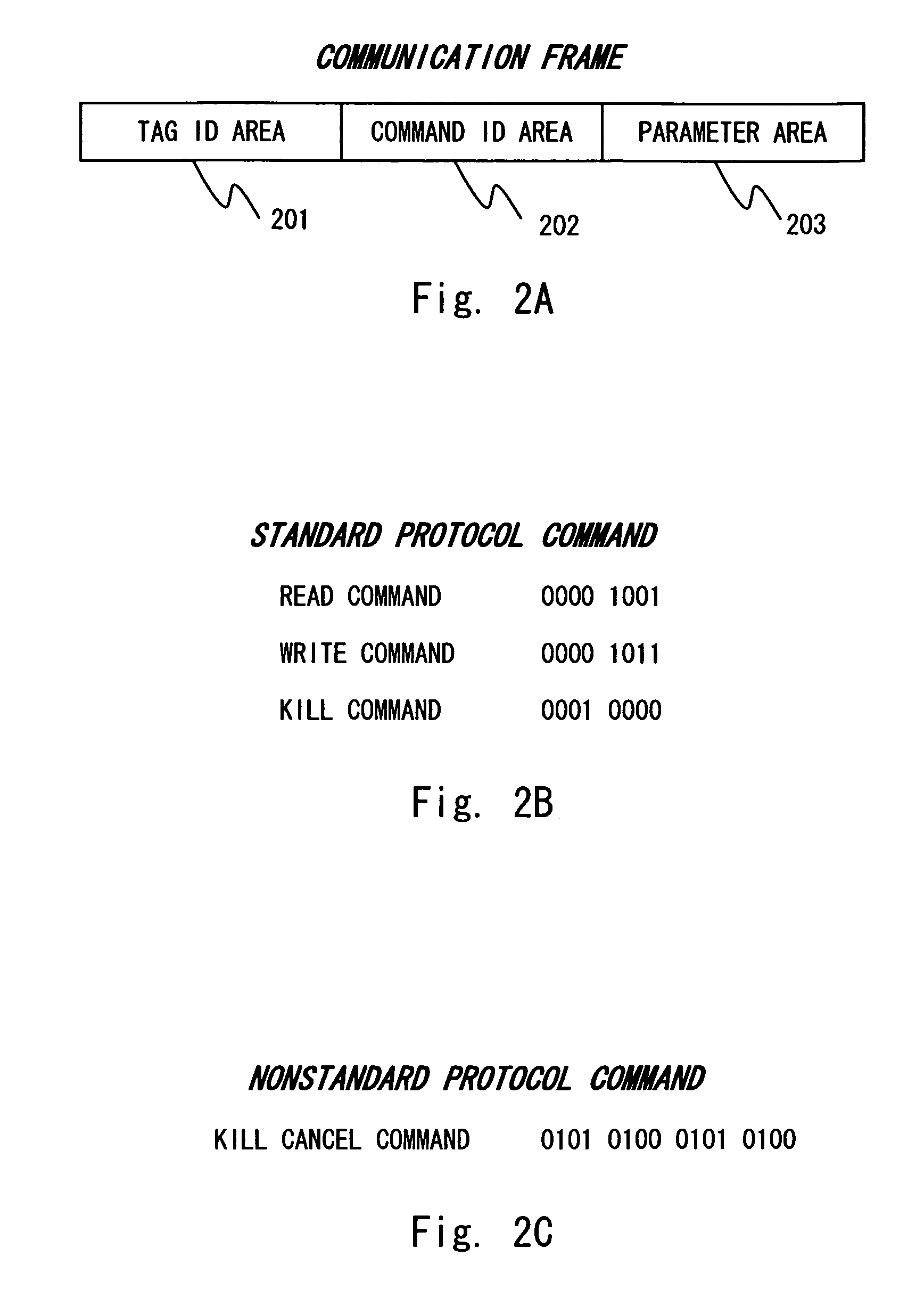
[0088] A communication frame transmitted / received in this embodiment is similar to that of the first embodiment as shown in FIGS. 2A to 2C, but in the case of the KILL cancel command, the parameter area 203 stores encoded data. The encoded data is data prepared by encoding plaintext data with a predetermined encryption key by use of the reader / writer 2.

[0089]FIG. 7 shows the configuration of the command analyzing unit 151, the command executing unit 152, and the system area 161 of this embodiment. The tag of this embodiment includes, in addition to the components of ...


PUM


Abstract

By canceling the invalidation, there is provided an IC tag that can be reused after the IC tag's function was invalidated. An IC tag according to an embodiment operates in accordance with a standard protocol and a non-standard protocol and includes a control circuit for switching an operational mode, when receiving a KILL command during an operation based on the standard protocol, to an invalidated state based on the non-standard protocol, and when receiving a KILL cancel command during an operation based on the non-standard protocol, to a normal state based on the standard protocol.

Description

BACKGROUND OF THE INVENTION [0001] 1. Field of the Invention [0002] The present invention relates to an IC tag, an IC tag controlling method, and an IC tag system. In particular, the present invention relates to an IC tag, IC tag controlling method, and an IC tag system which is operated in accordance with a predetermined communication protocol. [0003] 2. Description of Related Art [0004] In recent years, attentions have been paid to a technique regarding RFID (Radio Frequency Identification) as a product automatic identifying technique for affixing an IC tag having product specific information written thereto, and scanning this information using a radio antenna to manage a product in real time, in merchandise logistics management at the factory and article management at a retail shop. RFID has a merit apart from a bar code technique and the others that RFID is capable to read data from several IC tag at once and rewrite data stored in the IC tag. [0005] The above RFID IC tag (herei...

Claims


Application Information

Patent Timeline
IPC IPC(8): H04Q5/22G06F21/60G06F21/79
CPCG06K19/0723
Inventor AKIYAMA, KAZUHIROSATOU, KOUTAROUIGARASHI, HATSUHIDE
Owner NEC ELECTRONICS CORP
Why Eureka
Try Eureka