Ultrasonic object detector
- Summary
- Abstract
- Description
- Claims
- Application Information
AI Technical Summary
Benefits of technology
Problems solved by technology
Method used
Image

Examples
first embodiment
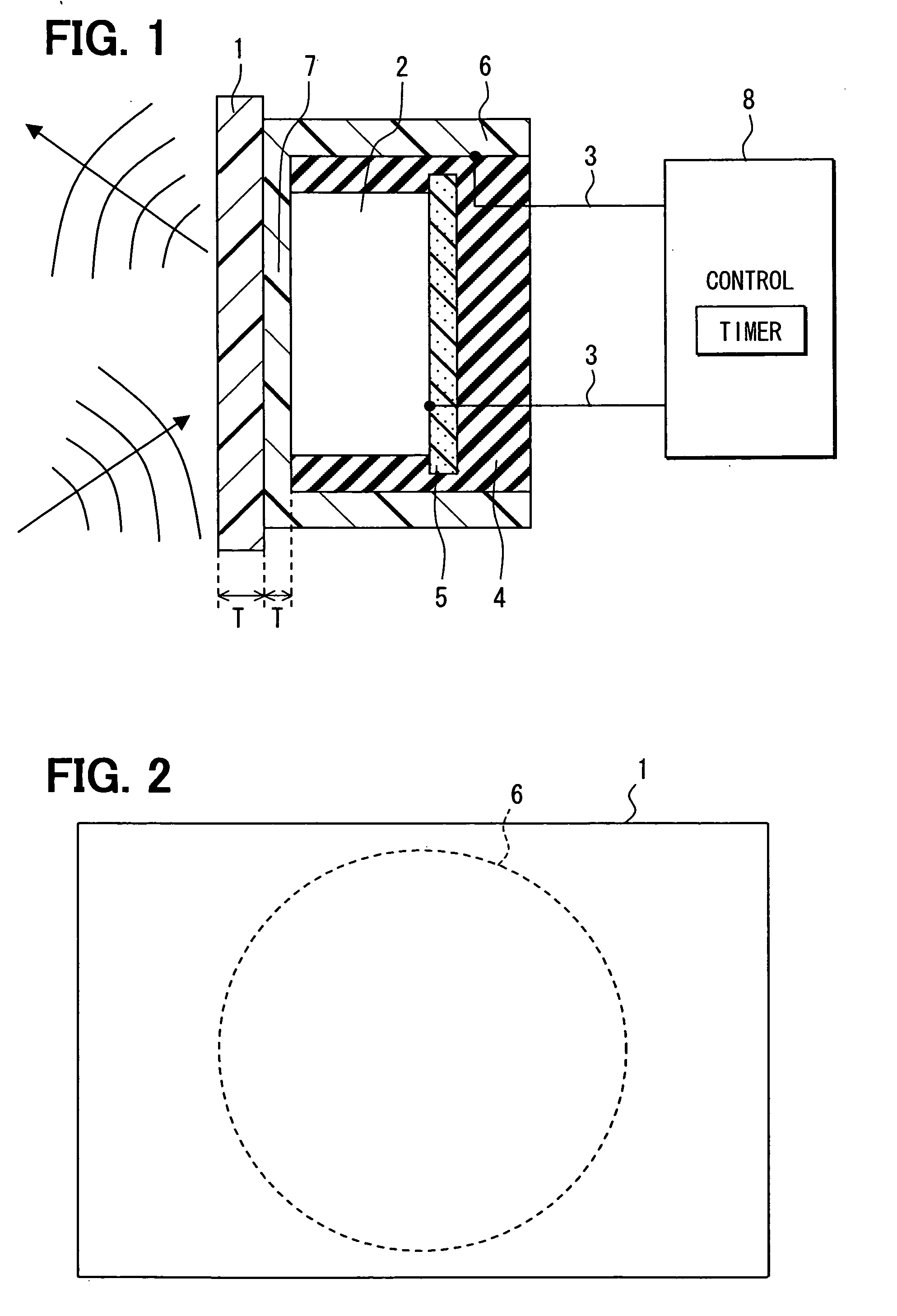
[0018] According to a first embodiment shown in FIGS. 1 and 2, an ultrasonic object detector is constructed with an ultrasonic sensor, which includes a piezoelectric vibrator 2, lead wires 3, a vibration absorber 4, a sound-absorbing member 5 and a housing 6 of a cylindrical shape. The object detector also includes an electronic control circuit 8. The ultrasonic sensor is mounted to be in contact with the back side of a wall of a bumper 1 of a vehicle. The wall of the bumper 1 forms a part of an outer contour of the vehicle. Thus, the ultrasonic sensor is concealed in the bumper 1 and not exposed to an exterior of the bumper 1.
[0019] The piezoelectric vibrator 2 is a piezoelectric ceramic produced by press-firing a powder of a metal oxide such as barium titanate and is disposed on a bottom surface portion 7 of the housing 6. When a pulse voltage is applied from the lead wires 3 from the control circuit 8, the piezoelectric vibrator 2 undergoes the distortion due to dielectric polar...
second embodiment
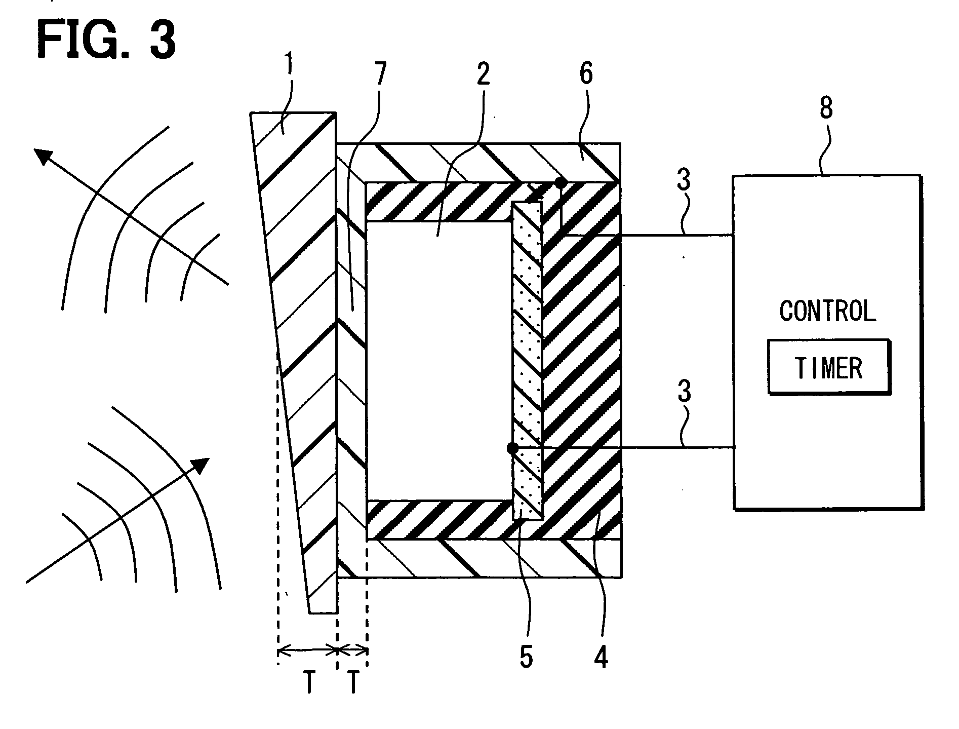
[0026] In a second embodiment shown in FIG. 3, the bumper 1 is so constructed as to possess a varying (non-uniform) thickness.
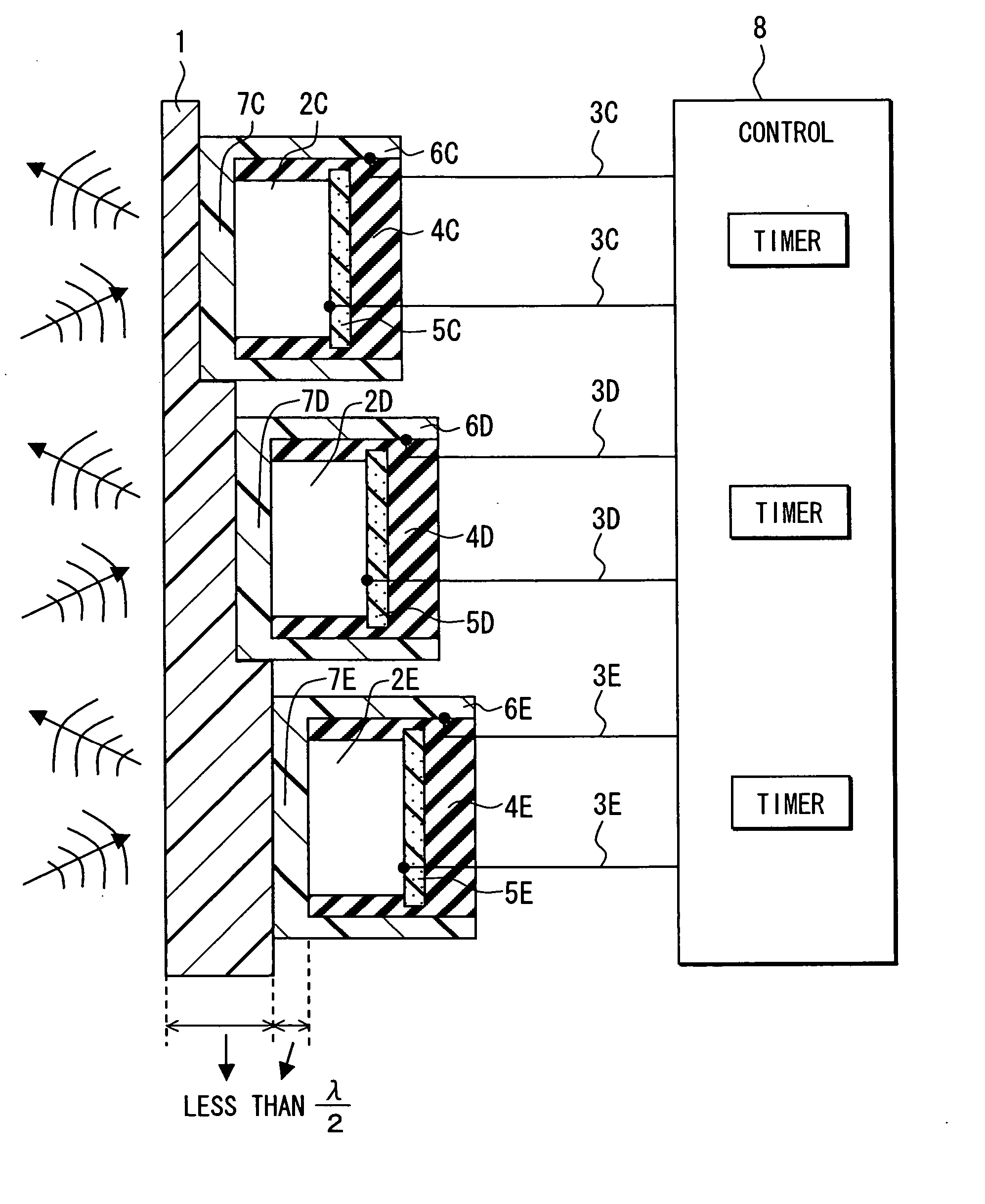
[0027] Specifically, the bumper 1 has a thickness which is one-half the wavelength λ of ultrasonic waves at a portion that comes in contact with the axis of cylinder of the ultrasonic sensor. The thickness is greater than one-half the wavelength λ of ultrasonic waves at a portion that comes in contact with the upper portion of the ultrasonic sensor, and the thickness is smaller than one-half the wavelength λ of ultrasonic waves at a portion that comes in contact with the lower portion of the ultrasonic sensor. This assures efficient transmission and reception of ultrasonic waves even when the wavelength of the ultrasonic waves has changed due to a change in the temperature. Further, the time until the ultrasonic waves generated by the piezoelectric vibrator 2 is radiated to the exterior of the vehicle varies in small amounts depending upon the portions where...
third embodiment
[0029] In a third embodiment shown in FIG. 4, a sensitivity-adjusting member 9 is plate-shaped and attached to the back side of the bumper 1 as part of the bumper 1.
[0030] Specifically, the sensitivity-adjusting member 9 is made of a material having a modulus of elasticity that varies little depending upon the temperature, is so constructed as to be in agreement with the shape of the bottom surface portion 7 of the housing 6, and is fitted into a recessed portion formed on the back side of the bumper 1. By using the material having a modulus of elasticity that varies little depending upon the temperature as a sensitivity-adjusting material, it is allowed to suppress a change in the wavelength of ultrasonic waves propagating through the sensitivity-adjusting material caused by a change in the temperature and to enhance the propagation efficiency. Like the thicknesses of the bumper 1 and of the bottom surface portion 7 of the housing 6 of the vehicle, the thickness of the sensitivity...
PUM
 Abstract
Description
Claims
Application Information
 - R&D
- Intellectual Property
- Life Sciences
- Materials
- Tech Scout
- Unparalleled Data Quality
- Higher Quality Content
- 60% Fewer Hallucinations
Browse by: Latest US Patents, China's latest patents, Technical Efficacy Thesaurus, Application Domain, Technology Topic, Popular Technical Reports.
© 2025 PatSnap. All rights reserved.Legal|Privacy policy|Modern Slavery Act Transparency Statement|Sitemap|About US| Contact US: help@patsnap.com