Image pickup optical systems, image pickup apparatuses and digital apparatuses

a technology of optical systems and image pickups, applied in the field of image pickup optical systems, image pickup apparatuses and digital apparatuses, can solve the problems of prisms and mirrors without optical power, photographer's shutter chances missed, and inability to achieve the effect of reducing the cost, suppressing the degradation of image quality, and excellent optical performan

Inactive Publication Date: 2007-02-01
KONICA MINOLTA OPTO
View PDF4 Cites 106 Cited by
  • Summary
  • Abstract
  • Description
  • Claims
  • Application Information

AI Technical Summary

Benefits of technology

[0010] It is an object of the present invention to optimize a compact image pickup optical system having excellent optical performance while suppressing the increase of the cost, particularly the shape of the emission surface of a reflection prism therein to provide an image pickup optical system and an image pickup apparatus incorporating such an image pickup optical system which can be suitably mounted on a cellular phone or a portable information terminal having a small thickness and can suppress the degradation of the image quality due to unnecessary light beams while enabling compaction.

Problems solved by technology

However, such image pickup optical systems having retractable construction involve complication of the structure of the barrel thereby increasing the cost.
Further, in cases where the lenses are structured to be evolved after power-on of the apparatuses, it will take predetermined time before the completion of preparation for photographing, which may cause the problem that the photographer misses shutter chances even if he or she finds an object that he or she wants to photograph during the time.
However, such prisms and mirrors have no optical power and are equivalent to a glass flat plate and an air space.
Accordingly, such additional components (prisms or mirrors) which will not contribute to the optical performance are required, which increases the number of components, thus increasing the cost.
However, if the prisms are provided with optical power in such a manner as disclosed in JP-A No. 2004-264343, JP-A No. 2004-264585 and JP-A No. 2004-212737, this will cause unavoidable unnecessary light beams (stray light) incident to the prisms to be reflected by the emission surfaces and the reflection surfaces of the prisms toward the image surface together with light beams propagating along the optical axis and enter the image pickup device, which may cause ghosts and the like, thus degrading the image quality, as will be described in detail on the basis of FIGS. 3 and 4.

Method used


Image

  • Image pickup optical systems, image pickup apparatuses and digital apparatuses
  • Image pickup optical systems, image pickup apparatuses and digital apparatuses
  • Image pickup optical systems, image pickup apparatuses and digital apparatuses

Examples


first embodiment

[0134]FIG. 15 is a longitudinal cross-sectional view illustrating the structure of an image pickup optical system 51A according to a first embodiment, taken along an optical axis (AX). FIG. 15 illustrates the placement of optical devices at a state where they are focused at infinity. In FIG. 15 (FIGS. 16 to 29), there is further illustrated the general outline of the path of light incident from an object, and the center line of the optical path is the optical axis (AX).

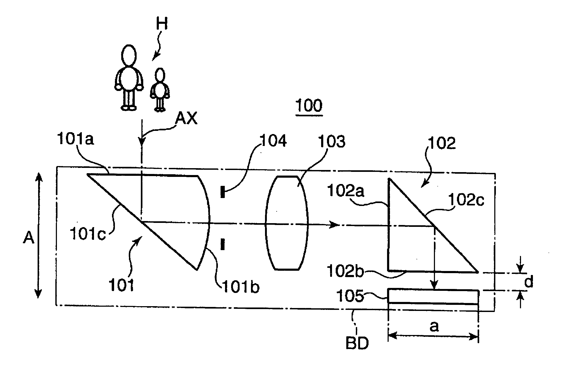
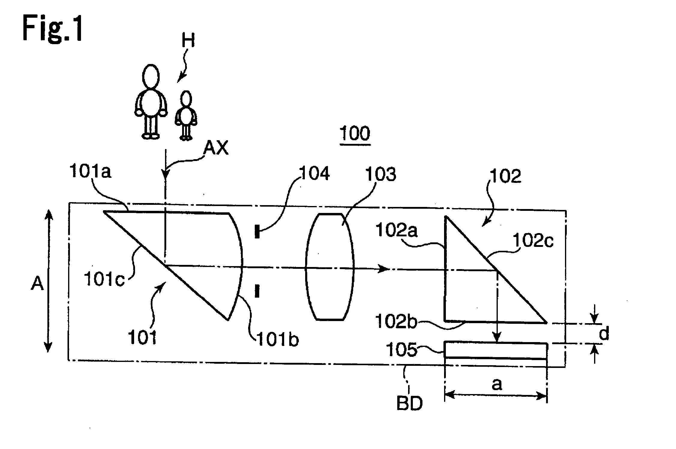
[0135] The image pickup optical system 51A according to the present embodiment is structured to include a first reflection prism of a compound type having positive optical power in its entirety (PR1; corresponding to the incidence-side prism 101 in FIG. 1), a first lens (L1) formed from a double-convex positive lens (a lens having positive optical power), a second lens (L2) formed from a positive meniscus lens which is convex at its object side, and a third lens (L3) formed from a compound lens having positive optica...

second embodiment

[0144]FIG. 18 is a longitudinal cross-sectional view illustrating the structure of an image pickup optical system 52 according to a second embodiment, taken along an optical axis (AX). The image pickup optical system 52 according to the second embodiment is structured to include a first reflection prism (PR1) having positive optical power in its entirety, an optical diaphragm (ST) for adjusting the light quantity, a plane parallel plate (PL), a first lens (L1) made of a double-convex positive lens, a second lens (L2) made of a positive meniscus lens having a convex surface at its object side, and a third lens (L3) made of a positive meniscus lens having a convex surface at its object side. Further, an image pickup device (SR) is placed near the image side of the third lens (L3).

[0145] The first reflection prism (PR1) has an emission surface (S1) having negative optical power, an emission surface (S3) having positive optical power, and a flat-shaped reflection surface (S2) on the op...

third embodiment

[0147]FIG. 20 is a longitudinal cross-sectional view illustrating the structure of an image pickup optical system 53 according to a third embodiment, taken along an optical axis (AX). The image pickup optical system 53 according to the third embodiment is structured to include a first reflection prism (PR1) having positive optical power in its entirety, an optical diaphragm (ST) for adjusting the light quantity, a first lens (L1) made of a double-convex positive lens, a second lens (L2) made of a double-concave negative lens, and a second reflection prism (PR2) having positive optical power in its entirety. Further, a plane parallel plate (PL) and an image pickup device (SR) are placed near the emission surface of the second reflection prism (PR2).

[0148] The first reflection prism (PR1) has an incidence surface S1 having negative optical power, an emission surface S3 having positive optical power, and a flat-shaped reflection surface S2 on the optical path between the incidence sur...


PUM


Abstract

The present invention provides image pickup optical systems capable of suppressing the degradation of the image quality due to unnecessary light beams while attaining compaction by optimizing the shapes of the emission surfaces of reflection prisms. The image pickup optical system includes an incidence-side prism for reflecting incident light while folding it by about 90 degree and an image-surface side prism. An image pickup device is placed near the emission surface of the image-surface side prism. The incidence-side prism is formed to have a convex emission surface. This can reduce the amount of the unnecessary light beams (stray light) reflected by the aforementioned reflection surface and also causes the unnecessary light beams reflected by the emission surface and the reflection surface to be diffused, thereby significantly reducing the amount of unnecessary light beams directed to the light receiving surface of the image pickup device. This can suppress the occurrence of ghosts and the like due to unnecessary light beams as aforementioned.

Description

[0001] The present application claims priority to Japanese Patent Application No. 2005-216318 filed on Jul. 26, 2005, the entire contents of which are hereby incorporated by reference. BACKGROUND OF THE INVENTION [0002] 1. Field of the Invention [0003] The present invention relates to image pickup optical systems, image pickup apparatuses and digital apparatuses incorporating the image pickup optical systems. [0004] 2. Description of the Related Art [0005] In recent years, there has been prominently advanced the widespread use of digital still cameras, digital video cameras and digital apparatuses such as camera-equipped cellular phones and portable information terminals (PDAs: Personal Digital Assistants), and there have been steeply increased the numbers of pixels and the functions of the image pickup devices mounted on these apparatuses. Accordingly, there has been a need for image pickup optical systems with excellent optical performance for directing optical images of objects t...

Claims


Application Information

Patent Timeline
Patent Type & Authority Applications(United States)
IPC IPC(8): H04N9/07
CPCG02B5/04G02B13/002G02B13/0065H04N5/2254G02B13/009G02B17/086G03B17/00G02B13/007
Inventor KONNO, KENJI
Owner KONICA MINOLTA OPTO
Why Eureka
Try Eureka