Novel computer controlled prosthetic knee device

a computer controlled, knee-mounted technology, applied in the field of prosthetic knees, can solve the problems of increasing cost, burdening users, and complex knees that incorporate computer controlled actuators, and achieve the effects of less cost, energy saving, and light weigh

Active Publication Date: 2007-02-01
PROTEOR USA LLC
View PDF2 Cites 66 Cited by
  • Summary
  • Abstract
  • Description
  • Claims
  • Application Information

AI Technical Summary

Benefits of technology

[0004] A prosthetic knee provides a single axis of rotation and includes a hydraulic damping cylinder, a microprocessor, and sensors. Based on input from the sensors, the microprocessor selects a flow path within the hydraulic cylinder in order to provide the proper amount of knee resistance to bending for a given situation. The resistance of each flow path within the hydraulic cylinder is manually preset. Changes in gait speed are accommodated by employing a hydraulic damper with intelligently designed position sensitive damping. Moreover, the knee need not be un-weighted to transition from the stance phase to the swing phase of gait. As a result, the knee safely provides a natural, energy efficient gait over a range of terrains and gait speeds and is simpler, less costly, and lighter weight than the prior art.

Problems solved by technology

Current prosthetic knees that incorporate computer controlled actuators are relatively complex and heavy, which both increases cost and is burdensome to the user.

Method used


Image

  • Novel computer controlled prosthetic knee device
  • Novel computer controlled prosthetic knee device
  • Novel computer controlled prosthetic knee device

Examples


Embodiment Construction

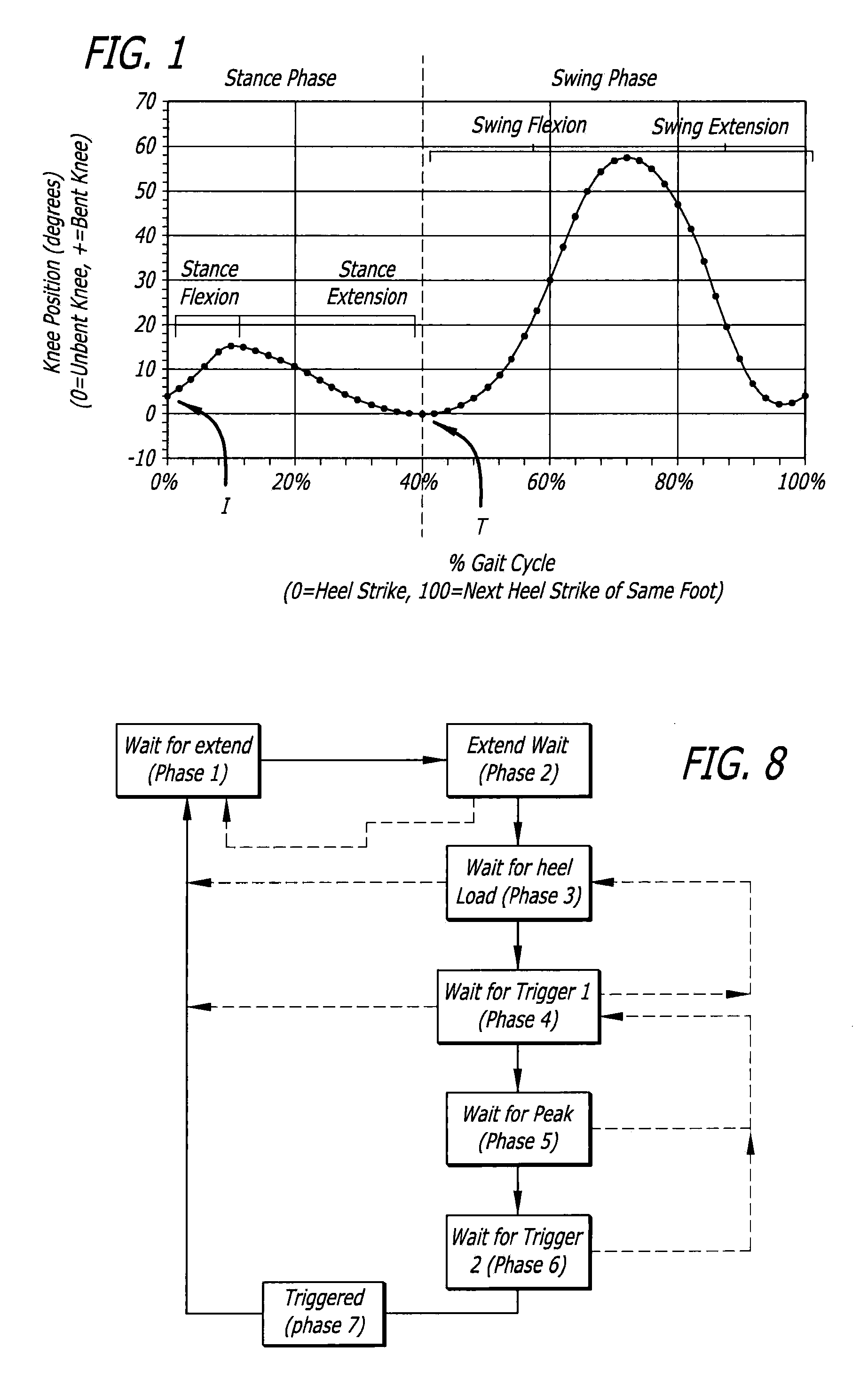
[0025] Makers of prosthetic knees have long attempted to mimic a natural walking gait. For purpose of illustration, this may be understood to be a reference to an exemplary walking gait cycle (level ground) as is graphically presented in FIG. 1. The chart depicts the knee position, along the y-axis, for an observed leg with respect to a percentage of gait cycle, along the x-axis. In the graph, the gait cycle initiates as the heel of the observed leg strikes the ground.

[0026] For each leg, a walking gait can be divided into two phases, a stance phase and a swing phase. The stance phase is defined as the period of time during which the foot of the observed leg is weighted. The swing phase is defined as the period of time when the foot of the observed leg is un-weighted. As a point of reference, the transition (T) from the stance phase to swing phase occurs at about 40 percent of the gait cycle.

[0027] The stance phase of a walking gait begins as the heel strikes the ground, indicated...


PUM


Abstract

A prosthetic knee provides a single axis of rotation and includes a hydraulic damping cylinder, a microprocessor, and sensors. Based on input from the sensors, the microprocessor selects a flow path within the hydraulic cylinder in order to provide the proper amount of knee resistance to bending for a given situation. The resistance of each flow path within the hydraulic cylinder is manually preset. Changes in gait speed are accommodated by employing a hydraulic damper with intelligently designed position sensitive damping. Moreover, the knee need not be un-weighted to transition from the stance phase to the swing phase of gait. As a result, the knee safely provides a natural, energy efficient gait over a range of terrains and gait speeds and is simpler, less costly, and lighter weight than the prior art.

Description

BACKGROUND OF THE DISCLOSURE [0001] The present disclosure relates generally to prosthetic devices and, more particularly, to prosthetic knees imparted with electronically improved motility and safety. [0002] Attempts have been made to overcome the drawbacks associated with the function of prosthetic knees by incorporating actuators that are actively, or computer, controlled. Based on inputs from sensors, the computer controls the amount of resistance provided by the actuator in order to adapt to changes in terrain and gait speed and decide when the transition from stiff to loose, or vice versa, should occur, thereby increasing safety, improving gait symmetry, and increasing energy efficiency. Current prosthetic knees that incorporate computer controlled actuators are relatively complex and heavy, which both increases cost and is burdensome to the user. Among the attempts to address the instant problems are found the following U.S. Pat. Nos. 6,764,520 B2, 6,755,870 B1; 6,740,125 B2;...

Claims


Application Information

Patent Timeline
Patent Type & Authority Applications(United States)
IPC IPC(8): A61F2/64A61F2/70
CPCA61F2/642A61F2/68A61F2002/5006A61F2002/7635A61F2002/741A61F2002/745A61F2002/748A61F2002/704A61F2/70A61F2/741A61F2/748A61F2/74
Inventor PALMER, MICHAEL L.BISBEE, CHARLES R. III
Owner PROTEOR USA LLC
Why Eureka
Try Eureka