Pool cleaning robot

Inactive Publication Date: 2007-02-08
MAYTRONICS
View PDF12 Cites 64 Cited by
  • Summary
  • Abstract
  • Description
  • Claims
  • Application Information

AI Technical Summary

Benefits of technology

[0014] According to a still further aspect of the present invention, there is provided a wheel adapted for use with a pool cleaning robot and adapted to be received by a frame of the robot. The wheel comprises a longitudinal axis along its length, a track receiving

Problems solved by technology

In addition, the motion of the track imparts a rotation

Method used


Image

  • Pool cleaning robot
  • Pool cleaning robot
  • Pool cleaning robot

Examples


Embodiment Construction

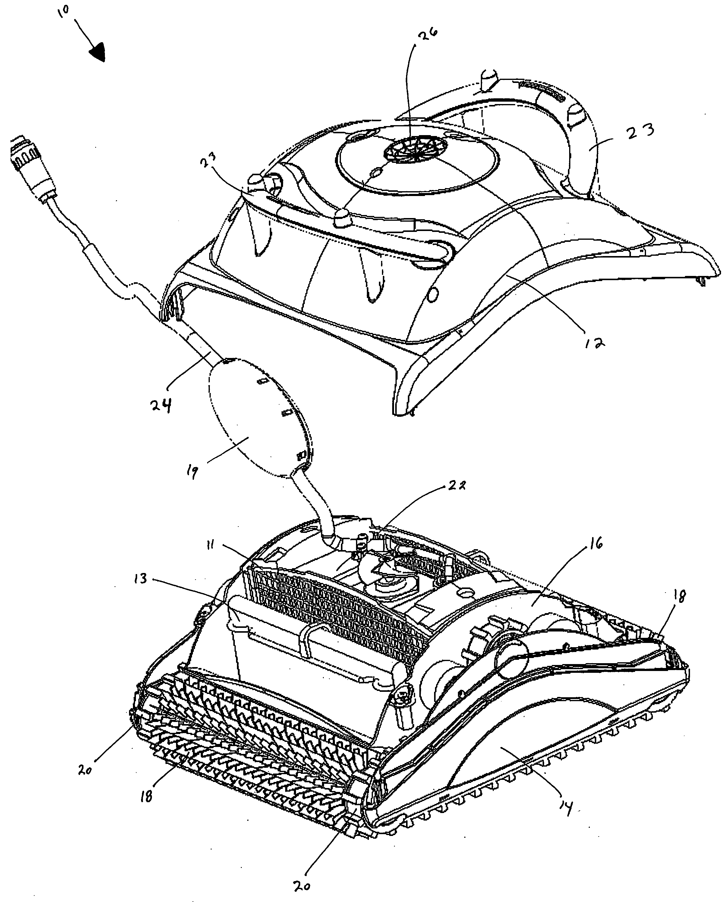
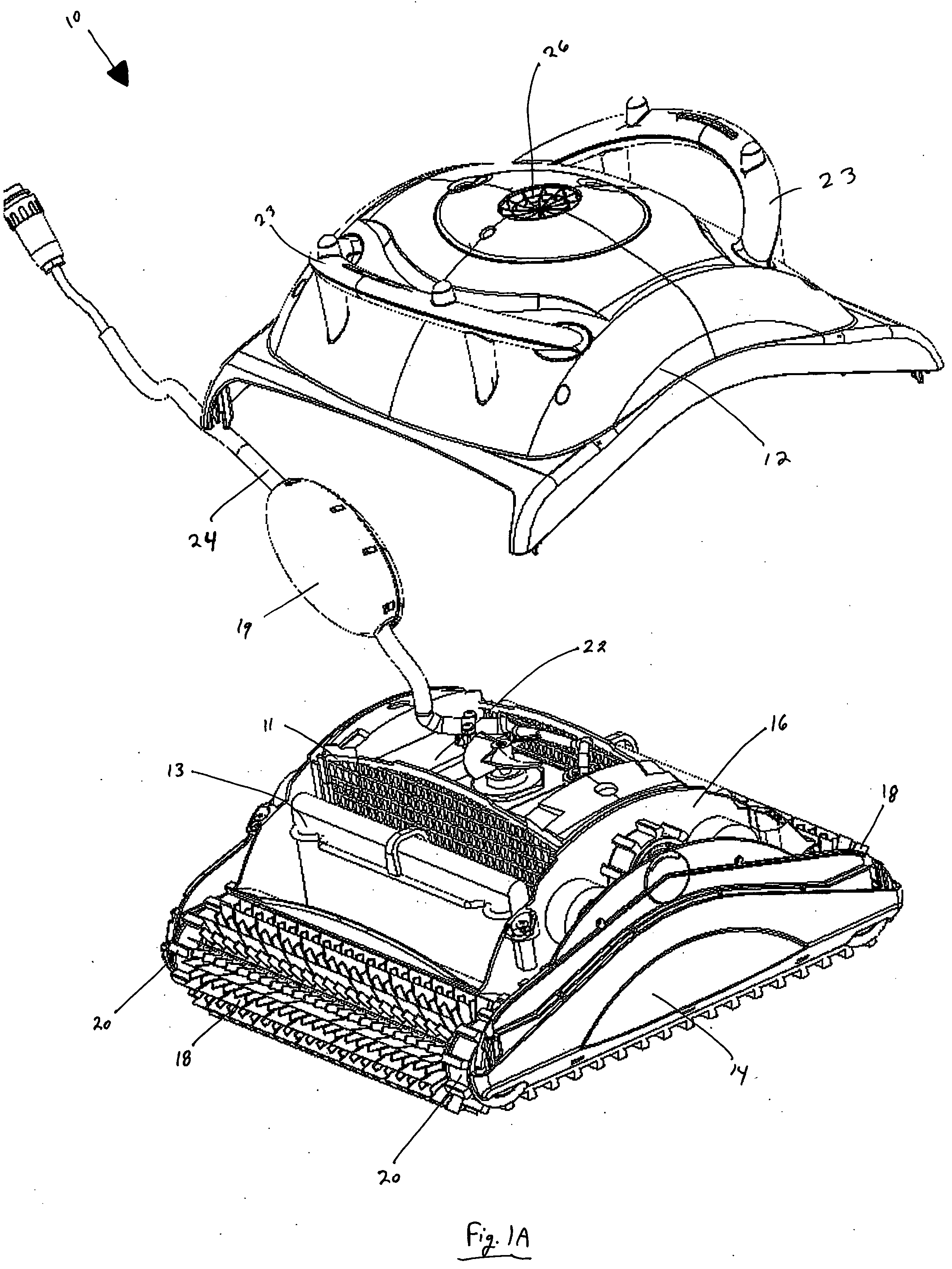
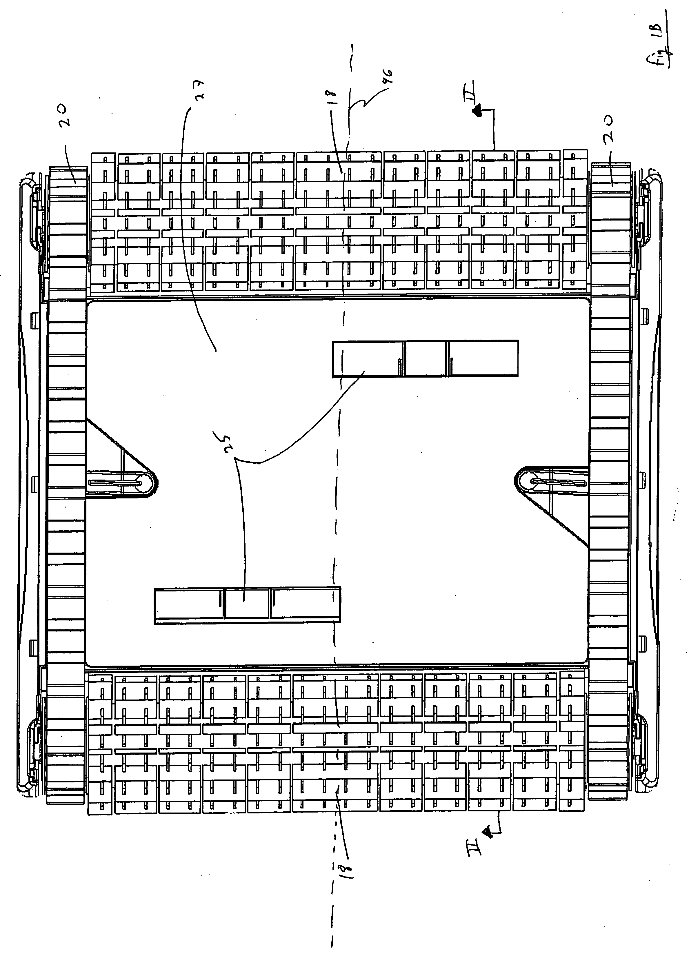
[0031] As seen in FIGS. 1A and 1B, there is provided a pool cleaning robot 10 in accordance with one embodiment of the present invention. The robot comprises an internal module 22 (seen in more detail in FIG. 2), a filter screen 11, a filter unit which comprises a filter bag 13 and a bottom panel 27, front and rear brushwheels 18, and two tracks 20. A housing, comprising an internal frame 16 (seen in more detail in FIG. 2), a cover 25, which comprises a pair of handles 23 and an outlet opening 26, and side panels 14, is also provided. The cover 12 and the side panels 14 are attached with screws to the internal frame 16. The robot further comprises a power cord 24 with a float 19 and inlets 25 formed in the bottom panel 27.

[0032]FIG. 2 illustrates the frame 16. It is integral and comprises two sidewalls 28 and two outwardly curved front / back walls 30 (since the robot is bidirectional, each of these walls may be alternately a front wall and a back wall, depending on the direction of ...


PUM


Abstract

A pool cleaning robot comprising a frame, at least one inlet, at least one outlet, and a motor carrying module. The robot further comprises a filter unit mountable to the frame. The filter unit has a filter bag with an inlet facing surface and an outlet facing surface. The robot further comprises a filter cavity formed between the outlet facing surface of the filter bag and the frame. The frame has an open area above the cavity. The open area faces the outlet and is designed for the insertion therethrough of the module into the filter cavity when the filter unit is mounted to the frame.

Description

FIELD OF THE INVENTION [0001] This invention relates to devices for cleaning swimming pools, basins, and the like. More particularly, the invention relates to an automatic self-propelled cleaning robot. BACKGROUND OF THE INVENTION [0002] Pool cleaning robots which automatically scan the floor and / or sidewalls of a swimming pool are well known in the art. These units are powered internally, by one or more battery packs, or externally, by way of a power cable. A robot of this type typically comprises a drive motor, a pump motor with an impeller, a filter, brushwheels, and a track. All of these components are contained within a housing. The housing comprises inlets at the bottom, and an outlet at the top. The robot comprises several sections, which permits at least partial disassembly of the robot. [0003] The drive motor drives the track, which propels the robot. In addition, the motion of the track imparts a rotation to the brushwheels, which scrubs the surface of the pool. [0004] The...

Claims


Application Information

Patent Timeline
IPC IPC(8): E04H4/16
CPCE04H4/1654
Inventor GARTI, EFRAIM
Owner MAYTRONICS
Why Eureka
Try Eureka