Sheet material cutting unit and printing device

a cutting unit and printing device technology, applied in the direction of manufacturing tools, saw chains, instruments, etc., can solve the problems of increasing the capacity of the motor for driving the movable blade b>, the need for further increase, and the increase in the cost, so as to eliminate the need for maintenance and improve the cutting quality of sheet materials. , the effect of stable sheet material quality

Inactive Publication Date: 2007-02-08
SEIKO INSTR INC
View PDF4 Cites 18 Cited by
  • Summary
  • Abstract
  • Description
  • Claims
  • Application Information

AI Technical Summary

Benefits of technology

[0022] A fourth aspect of the present invention resides in a sheet material cutting unit further including a second sheet material retaining means is provided upstream from the sheet material cutting position in the sheet material transfer direction for retaining the sheet material on the sheet material transfer path during the cutting. Since the sheet material is retained before and after the cutting position, the sheet material can be retained with more stability to carry out accurate cutting irrespective of the system adopted by a printing portion.
[0023] A fifth aspect of the present invention resides in a printing device provided with the sheet material cutting unit according to the first to fourth aspects, which includes a printing portion provided upstream from the sheet material cutting position in the sheet material transfer direction for printing on the sheet material. This makes it possible to provide the printing device which eliminates the need for maintenance due to a jammed sheet material or the like and which has stable sheet material cutting quality.
[0024] A sixth aspect of the present invention resides in a printing device provided with the sheet material cutting unit according to the fourth aspect, in which the second sheet material retaining means includes: a thermal head for printing on the sheet material; and a platen roller opposed to the ...

Problems solved by technology

However, if the contact pressure is too high, frictional load applied to the fixed blade 108 and the movable blade 112 is increased, and thus, a problem is caused that the capacity of a motor for driving the movable blade 112 has to be increased further than necessary.
However, in the case of (1), though methods such as increasing the hardness of the material of the blades, increasing the robustness of the blades by quenching the blades themselves, and performing surface hardening process such as coating can be considered, these methods have a problem that the cost is increased.
Further, in the case...

Method used


Image

  • Sheet material cutting unit and printing device
  • Sheet material cutting unit and printing device
  • Sheet material cutting unit and printing device

Examples


second embodiment

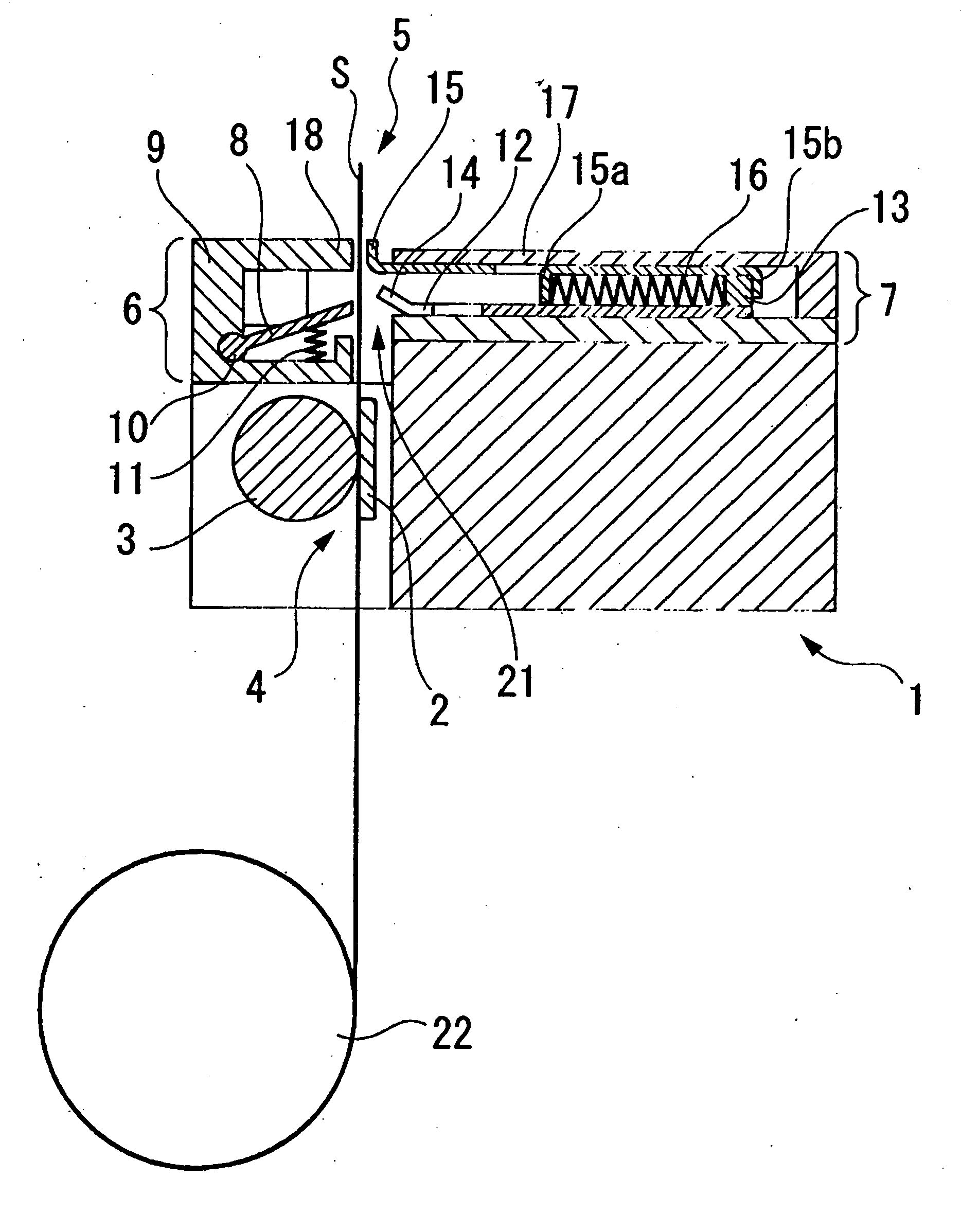
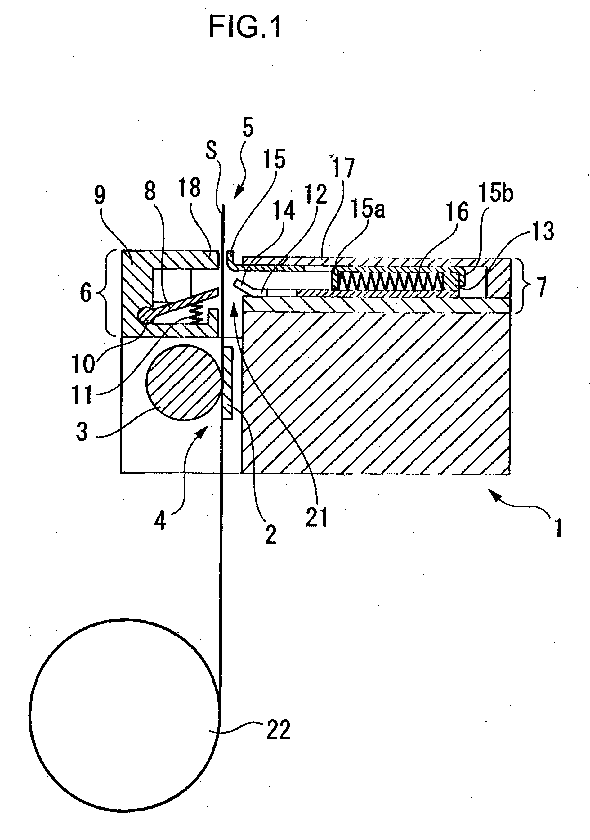
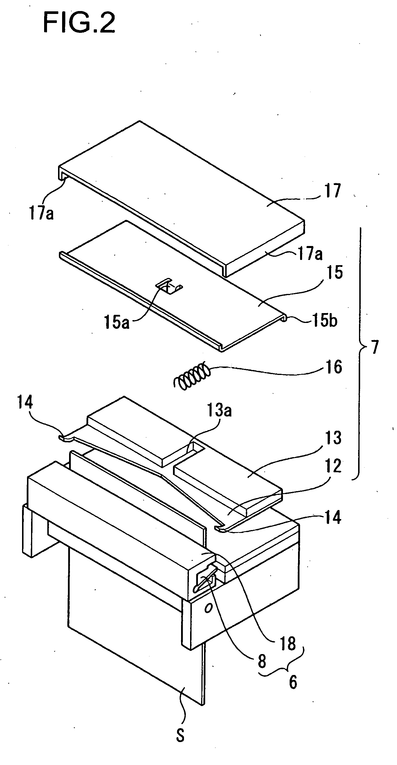
[0068]FIG. 4 illustrates a sheet material cutting unit according to the present invention.

first embodiment

[0069] A sheet material cutting unit 5b according to this embodiment has, in addition to the sheet material retaining means provided for the first embodiment, second sheet material retaining means provided downstream from the sheet material cutting position. More specifically, a second sheet material movably holding portion 25 is provided on an opposite side of the sheet material movably holding portion 15 with the movable blade 12 therebetween.

[0070] In this embodiment, a second movable blade holder 28 is provided on a back surface of the movable blade 12 with respect to a surface thereof to which the movable blade holder 13 is provided. The second movable blade holder 28 also has a notch portion 28a which corresponds to the notch portion 13a of the movable blade holder 13. Further, the second sheet material movably holding portion 25 also has a protrusion 25a and a bend 25b similarly to the case of the sheet material movably holding portion 15. A spring member 27 is provided in th...

third embodiment

[0076]FIG. 5 illustrates a sheet material cutting unit according to the present invention.

[0077] The movable blade 12 of a sheet material cutting unit 5c according to this embodiment is not provided with the sheet material movably holding portion provided for the first embodiment. Instead, sheet material fixedly holding portions 18a and 18b are provided with a plurality of air suction holes 22a and 22b. The holes connect with a suction pump. By sucking air through the holes just before the sheet material S is cut, the sheet material S can be retained by being sucked by the sheet material fixedly holding portions 18a and 18b. By continuing air suction to maintain the retention of the sheet material and thus preventing the sheet material S from falling when the movable blade 12 is horizontally moving with respect to the fixed blade 8 to cut the sheet material S, the cutting can be made stable.

[0078] Although, in this embodiment, the air suction holes 22 are provided for both the shee...


PUM

PropertyMeasurementUnit
Stabilityaaaaaaaaaa

Abstract

To provide a sheet material cutting unit which can retain the posture of a sheet material when the sheet material is cut such that a movable blade can bite the sheet material with stability. A sheet material fixedly holding portion provided in parallel with a fixed blade and a sheet material movably holding portion linked with a movable blade are provided downstream from a sheet material cutting position in a sheet material transfer direction to retain a sheet material from both sides of the sheet material when the sheet material is cut.

Description

BACKGROUND OF THE INVENTION [0001] 1. Field of the Invention [0002] The present invention relates to a sheet material cutting unit for cutting a long length of a printed sheet material at a desired position and to a printing device provided with the sheet material cutting unit. [0003] 2. Related Background Art [0004] Conventionally, as a sheet material cutting device, one for cutting a sheet material placed between a fixed blade and a movable blade by reciprocating the movable blade with respect to the fixed blade and sliding the two blades with respect to each other, “a cut-through type”, is widely known. [0005] Since such a sheet material cutting device can cut a sheet material with a simple drive, it is suitable to be mounted on a small printer device provided for a cash register or an ATM which issues a receipt. A sheet material cutting device described in Patent Document 1 is such the sheet material cutting unit. [0006] Here, operation of a conventional sheet material cutting u...

Claims


Application Information

Patent Timeline
IPC IPC(8): B26D1/00
CPCB26D1/085B26D7/025B26D7/2628G07B5/02B41J11/70G07B1/00B26D2007/2685Y10T83/929
Inventor KAWAGUCHI, KOUJI
Owner SEIKO INSTR INC
Why Eureka
Try Eureka