Weight-forward composite arrow shaft

a composite arrow shaft and weight-forward technology, applied in the field of weight-forward composite arrow shafts, can solve the problems of high levels of draw force reduction at full draw, variances of this magnitude cannot be optimally accommodated, and are too limber for heavier draw-weight bows equipped with heavy mass limbs, etc., to achieve significant stiffening, enhance the penetration potential of arrows, and increase the strength of reinforcements

Inactive Publication Date: 2003-04-29
SCHAAR JOHN G
View PDF4 Cites 28 Cited by
  • Summary
  • Abstract
  • Description
  • Claims
  • Application Information

AI Technical Summary

Benefits of technology

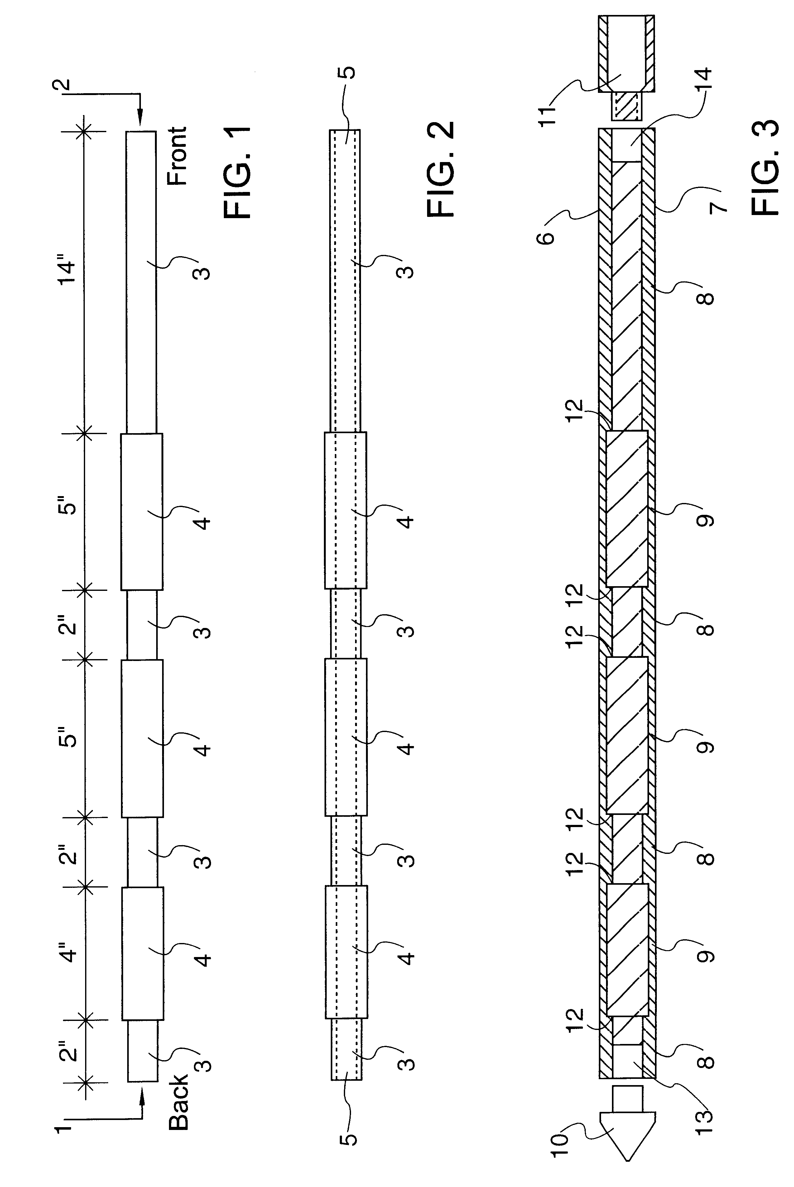
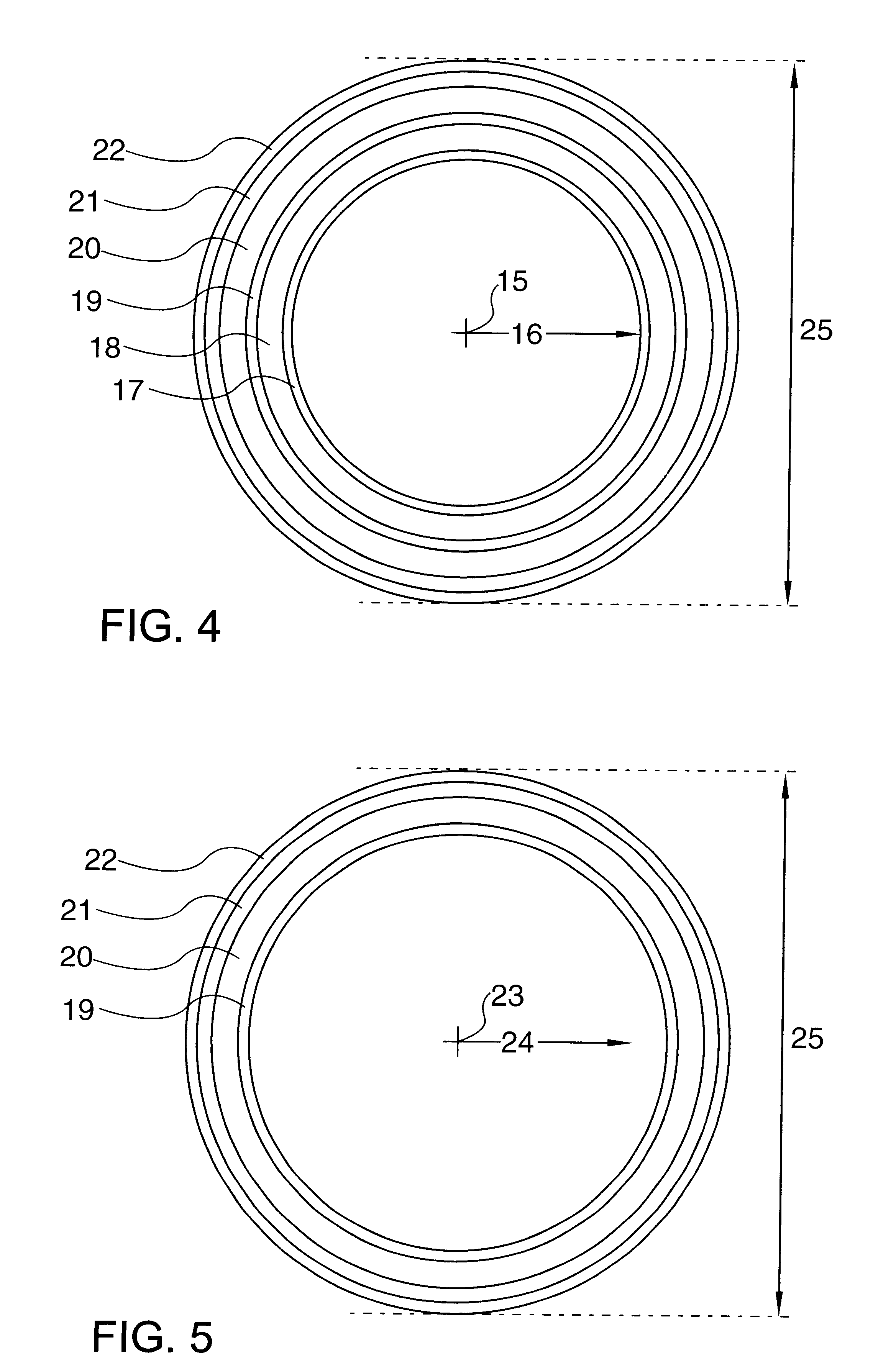
However, it is also the case that by selecting the core to be made of a porous material, that the adhesive bond between the core of the inventive arrow shaft, and the outside reinforcing materials in the inventive arrow shaft, will be more reliable than the adhesive bonds achieved in prior art composite shafts alluded to earlier, which employed non-porous mandrels overlaid by reinforcements, resulting in a shaft column having a somewhat barrel-shaped outside surface. The cementing of the nock and point inserts directly to the outer reinforcing material layers provides a third locking mechanism for precluding movement of the core materials at any point in time.
Retaining the core material, mechanically locked in place and cemented to the outside reinforcement materials, provides significant stiffening in the overall shaft column. The improved sectional density of the composite column, combines with greater reinforcement stiffness in a manner that produces further additional benefits in terms of enhancing the penetration potential of the arrow, enhancing accuracy, and quieting the downrange flight of the arrow. The added stiffness obtained by retention of the inner core material, coupled with the additionally reinforced front end of the shaft column, aids the shaft column in staying straight at the time of impact, and serves to maximize the amount of kinetic energy in the column that is concentrated in a single direction at the time of impact, thereby enhancing the penetration potential of arrows made using shafts of this invention.
The added stiffness, and the manner in which the core materials are joined to the outer reinforcement materials such that bending moments affecting any point along the shaft's length are both offset by materials on the opposite side of the shaft column, and by the underlying core materials, serves to dampen any harmonic vibrations imparted to the shaft column during acceleration, and thereby serves to restore stability more quickly, which positively impacts shooting accuracy, and also serves to reduce noise relating to harmonic vibrations in the shaft when such vibrations are present.
The inventive method of shaft construction yields another benefit not present in prior art composite shafts. The retention of the core materials serves to significantly improve the hoop strength of the shaft column at all points along it's length. Improved hoop strength serves to improve durability in the arrow when it comes in contact with sudden pressure coming against the side of the column, such as when a misdirected arrow inadvertently "skips" off of a log, tree branch, or rock.

Problems solved by technology

However, it has also proven to be the case that as compound bows continued to evolve after 1985, they often incorporated pulley systems that resulted in very high levels of draw force reduction at full draw.
Variances of this magnitude cannot be optimally accommodated by the prior art approaches described in U.S. Pat. Nos. 4,533,146 and 4,706,965, especially for hunting bows with relatively light draw weights.
Conversely, an given size arrow that was light enough to be optimal when used from a very light draw weight bow, with a very high percentage of draw force reduction at full draw, and with short draw length, with the draw length possibly made even shorter by use of an overdraw, would often either be too limber for heavier draw-weight bows equipped with heavy mass limbs, and having a low letoff percentage, or not weigh enough to properly load the limbs sufficiently to preclude a dry-fire effect in the heavier draw weight bow.
However, by 1990, continuing evolution in the compound bow area had significantly offset the usefulness of this aspect of these prior art references.
This approach still works, but because multiple shaft sizes may now be required, this approach does not offer as great a benefit level as was intended at the time the invention was made.
The trimmable components defined in prior art reference U.S. Pat. No. 4,533,146 are somewhat more costly to produce than are fixed-weight components, and require additional labor (trimming) prior to assembly.

Method used


Image

  • Weight-forward composite arrow shaft
  • Weight-forward composite arrow shaft
  • Weight-forward composite arrow shaft

Examples


Embodiment Construction

The preferred embodiment relates to an arrow shaft of a given size being constructed for use with hunting points, and which will, when incorporated into the construction of a finished arrow, effectively allow the utilization of a single set of fixed-weight, end-mounted components suitable for outfitting hunting arrows, for arrows of the given size of all lengths between 24" and 34". The preferred embodiment defines an arrow shaft that, when used to construct a finished hunting arrow, will yield a balance point that is within ten to fifteen percent in front of center when assembled with a single fixed-weight set of end-mounted components, when the given size arrow shaft is cut to any finished length between 24" and 34". The arrow shafts described in the preferred embodiment include features which, with minor modifications that would be obvious to one skilled in the art, would yield arrows suitable for other types of archery shooting as well.

FIG. 1 shows a side view of a solid, substa...


PUM


Abstract

An improved arrow shaft comprised of a core of substantially round, very lightweight, porous material, with the porous core having sections that have different diameters at various points along the length of the arrow shaft, with the lightweight core materials being overwrapped with different thickness' of reinforcing materials such that the resulting outside diameter of the finished arrow shaft has substantially parallel surfaces over the entire length of the shaft and the finished shaft has a substantially constant circumference and outside diameter along its entire length. The inventive composite arrow shaft incorporates different thickness' and weights of reinforcement materials, strategically placed along it's length, in a manner that results in providing, in an integral manner, proper front to back balance in the finished arrow, with the proper balance achieved by using the same weight point, point insert, nock, nock insert, and fletching materials, regardless of the length the shaft is cut off at. The preferred embodiment of the inventive arrow shaft includes end sections at each end that have greater thicknesses of reinforcement materials overlaying the core, than at other intermediate sections of the shaft, with the increased reinforcement materials at each end of the shaft serving to increase, in an integral manner, the strength of the shaft in these areas. The preferred embodiment of the inventive arrow shaft also includes at least one other section intermediate the end sections of the shaft that also has greater thicknesses of reinforcement materials along it's length than do some other sections of the shaft that are intermediate the additionally-reinforced end sections.

Description

II. PRIOR ART REFERENCESIII. BACKGROUND OF THE INVENTIONThe general background of the invention up until about 1984 was well described in prior art reference U.S. Pat. No. 4,533,146. This patent application incorporates that background section by reference. To that background reference, I now add the prior art reflected in U.S. Pat. Nos. 4,533,146 and 4,706,965, and the additional background which follows.References U.S. Pat. Nos. 4,533,146 and 4,706,965 sought to define a combination of arrow sub-components that could be assembled in a manner which, when combined, provided additional reinforcements in the area near each end of the arrow shaft, and near the center of the arrow shaft, and which could be configured, by trimming prescribed amounts of material from excessively long point inserts, nock inserts, points, and nocks, so as to achieve proper front-to-back balance in the finished arrow.It was found to be the case that, in 1984, a single very stiff arrow shaft could indeed be u...

Claims


Application Information

Patent Timeline
Patent Type & Authority Patents(United States)
IPC IPC(8): F42B6/04F42B6/00
CPCF42B6/04
Inventor SCHAAR, JOHN G.
Owner SCHAAR JOHN G
Why Eureka
Try Eureka