Thermal module

a technology of thermal modules and modules, applied in the field of thermal modules, can solve the problems of lowering the heat dissipation efficiency of thermal modules, both ways have their difficulties,

Inactive Publication Date: 2007-02-08
HON HAI PRECISION IND CO LTD
View PDF27 Cites 39 Cited by
  • Summary
  • Abstract
  • Description
  • Claims
  • Application Information

AI Technical Summary

Problems solved by technology

Both ways have their difficulties due to manufacturing and dimensional limitations.
Furthermore, the fin assembly is formed as a rectangular-shaped configuration, which does not match the configuration of the bending portion of the heat pipe.
Thus, the heat at the condenser section is not totally directly transferred to the fin assembly from the heat pipes, which lowers the heat dissipation efficiency of the thermal module.

Method used


Image

  • Thermal module
  • Thermal module
  • Thermal module

Examples


Embodiment Construction

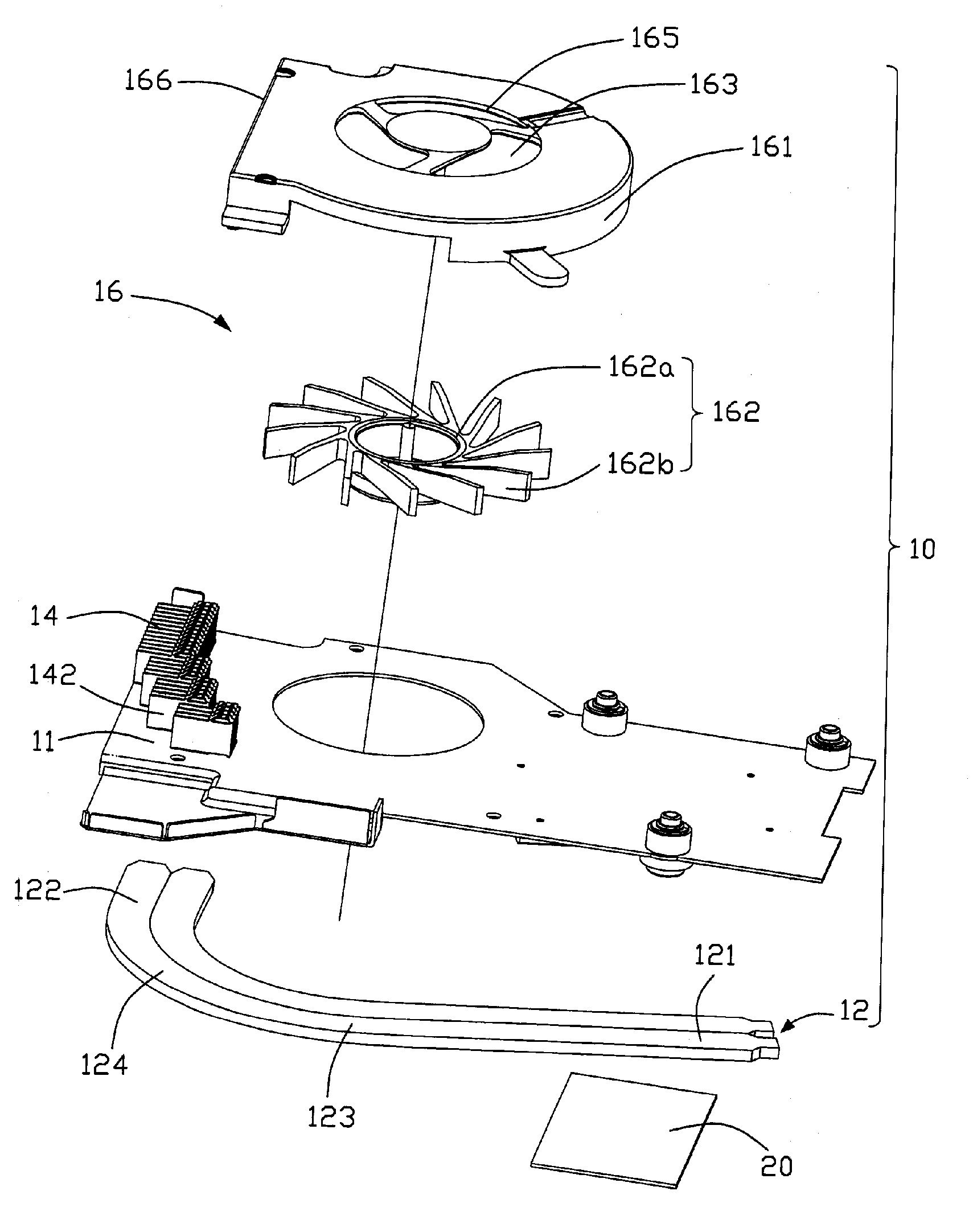
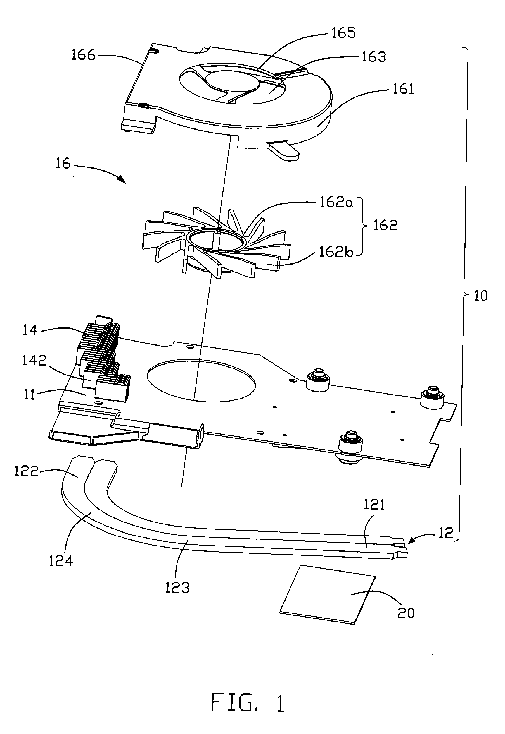
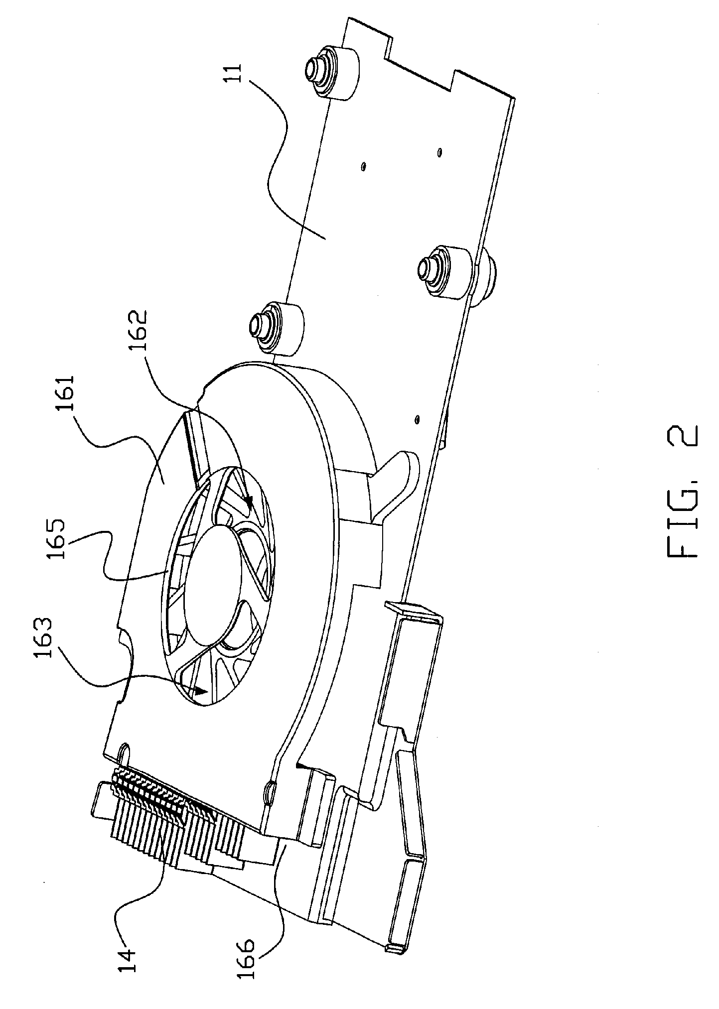
[0016] Referring to FIGS. 1 and 2, a thermal module 10 according to a preferred embodiment of the present invention is shown. The thermal module 10 includes a base plate 11, two heat pipes 12, a fin assembly 14, and a heat-dissipating fan 16.

[0017] The base plate 11 is made of materials having good heat conductive capability, and defines a lateral direction and a longitudinal direction perpendicular to the a lateral direction.

[0018] Referring to FIG. 3, the heat-dissipating fan 16 is a centrifugal blower mounted to an upper side of the base plate 11 for providing an airflow with a high air pressure. The fan 16 includes a casing 161, a stator (not shown) mounted in the casing 161, and a rotor 162 rotatably disposed around the stator. An accommodating space 163 is enclosed between the casing 161 and the base plate 11 for accommodating the stator and the rotor 162 therein. An air inlet 165 is defined in a top wall of the casing 161. The rotor 162 includes a hub 162a, and a plurality ...


PUM


Abstract

A thermal module (10) for dissipating heat from a heat-generating electronic component (20) includes a base plate (11), a heat-dissipating fan (16) mounted to one side of the base plate, at least a heat pipe (12) mounted to another side opposite to the one side of the base plate, and a fin assembly (14) mounted to an air outlet of the heat-dissipating fan. The heat pipe includes a bending portion (124). The fin assembly includes a portion (142) corresponding to the bending portion of the heat pipe. The fins of the portion of the fin assembly are arranged along an extension direction of the bending portion of the heat pipe.

Description

FIELD OF THE INVENTION [0001] The present invention relates generally to a thermal module, and more particularly to a thermal module for dissipating heat generated by electronic components. DESCRIPTION OF RELATED ART [0002] A thermal module generally includes a base plate, a blower mounted to a top side of the base plate, a rectangular-shaped fin assembly mounted at an outlet of the blower, and a plurality of heat pipes mounted to a bottom side of the base plate and thermally connecting a heat-generating electronic component with the fin assembly. [0003] Each of the heat pipes includes an evaporator section contacting with the heat-generating electronic component, a condenser section remote from the heat-generating electronic component and thermally contacting with the fin assembly, and an adiabatic section interconnecting the evaporator section and the condenser section. A bending portion is formed at the of the condenser section of the heat pipe so that an end portion of the conde...

Claims


Application Information

Patent Timeline
Patent Type & Authority Applications(United States)
IPC IPC(8): H05K7/20
CPCH01L23/427H01L23/467H01L2924/0002H01L2924/00F28D15/0275
Inventor HWANG, CHING-BAIHUNG, JUI-WEN
Owner HON HAI PRECISION IND CO LTD
Why Eureka
Try Eureka