Voltage regulator with prevention from overvoltage at load transients

a voltage regulator and load transient technology, applied in the direction of electric variable regulation, process and machine control, instruments, etc., can solve problems such as current sinking circuits, and achieve the effect of stable output voltag

Inactive Publication Date: 2007-02-08
GLOBAL MIXED MODE TECH
View PDF7 Cites 52 Cited by
  • Summary
  • Abstract
  • Description
  • Claims
  • Application Information

AI Technical Summary

Benefits of technology

[0008] In view of the above-mentioned problems, an object of the present invention is to provide a voltage regulator capable of preventing from overshooting and oscillating of the output voltage at load transients, thereby providing a stable output voltage.

Problems solved by technology

As an adverse result, the output voltage Vout is prone to oscillating at a high frequency and actually causes the current sinking circuit 14a or 14b to repeatedly turn the switching transistor PS or NS between on and off.

Method used


Image

  • Voltage regulator with prevention from overvoltage at load transients
  • Voltage regulator with prevention from overvoltage at load transients
  • Voltage regulator with prevention from overvoltage at load transients

Examples


Embodiment Construction

[0017] The preferred embodiments according to the present invention will be described in detail with reference to the drawings.

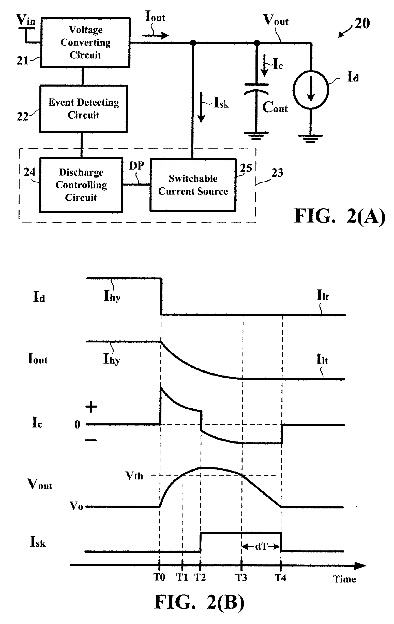
[0018]FIG. 2(A) is a circuit block diagram showing a voltage regulator 20 according to the present invention. Referring to FIG. 2(A), the voltage regulator 20 primarily includes a voltage converting circuit 21, an event detecting circuit 22, and a current sinking circuit 23. The current sinking circuit 23 primarily includes a discharge controlling circuit 24 and a switchable current source 25.

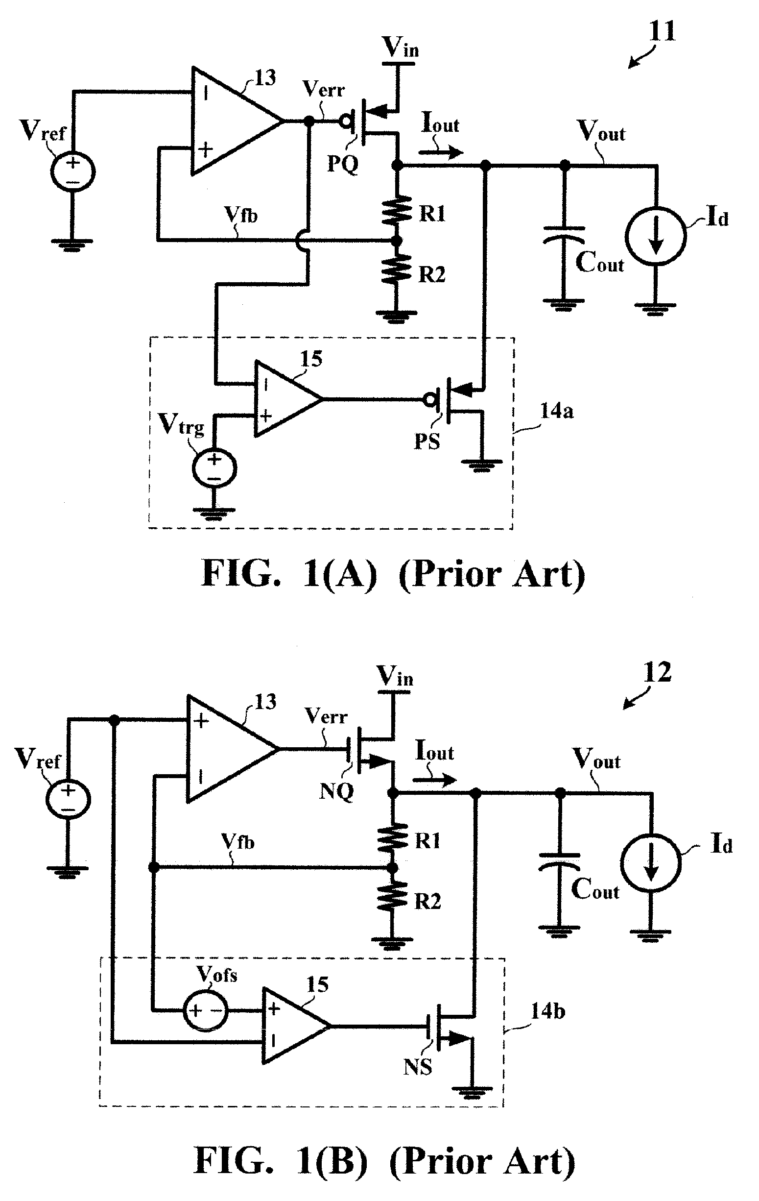
[0019] Speaking in general, the voltage converting circuit 21 is a type of circuit that converts an input voltage Vin into an output voltage Vout and supplies an output current Iout at the output voltage Vout through an output terminal in accordance with a requirement of a load Id. The voltage converting circuit 21 may be implemented by the linear regulator 11 or 12 shown in FIG. 1(A) or 1(B), i.e. consisting of a voltage divider, an error amplifier, and a transistor ...


PUM


Abstract

A voltage converting circuit has an output terminal for supplying an output current at an output voltage to a load. In response to a transient of the load, a current sinking circuit allows a current source to provide a sink current flowing from the output terminal of the voltage converting circuit into a ground potential. The sink current is finite and stable. When the output voltage decreases below a threshold voltage, the current sinking circuit allows the current source to keep providing the finite and stable sink current for an extension time, causing the output voltage to decrease from the threshold voltage to a regulated value.

Description

BACKGROUND OF THE INVENTION [0001] 1. Field of the Invention [0002] The present invention relates to a voltage regulator and, more particularly, to a voltage regulator capable of stabilizing output voltages at load transients. [0003] 2. Description of the Prior Art [0004]FIG. 1(A) is a circuit diagram showing a first example of a conventional linear regulator 11. The linear regulator 11 converts an input voltage Vin into an output voltage Vout, and supplies an output current lout in accordance with a requirement of a load Id. A resistive voltage divider formed of series-connected resistors R1 and R2 generates a feedback voltage Vfb representative of the output voltage Vout. Through comparing the feedback voltage Vfb and a predetermined reference voltage Vref, an error amplifier 13 generates and applies an error voltage Verr to a gate electrode of a transistor PQ. The drain-source current channel of the transistor PQ is connected between the input voltage Vin and the output voltage V...

Claims


Application Information

Patent Timeline
Patent Type & Authority Applications(United States)
IPC IPC(8): G05F1/10
CPCG05F1/571
Inventor LEE, RONG-CHINSU, FANG-TE
Owner GLOBAL MIXED MODE TECH
Why Eureka
Try Eureka