RFID reader having antenna with directional attenuation panels for determining RFID tag location

Inactive Publication Date: 2007-02-08
IBM CORP
View PDF8 Cites 69 Cited by
  • Summary
  • Abstract
  • Description
  • Claims
  • Application Information

AI Technical Summary

Benefits of technology

[0008] The attenuator can comprise 2 or more areas of reduced attenuation. The a

Problems solved by technology

This method is effective, but relatively expensive to implement

Method used


Image

  • RFID reader having antenna with directional attenuation panels for determining RFID tag location
  • RFID reader having antenna with directional attenuation panels for determining RFID tag location
  • RFID reader having antenna with directional attenuation panels for determining RFID tag location

Examples


Embodiment Construction

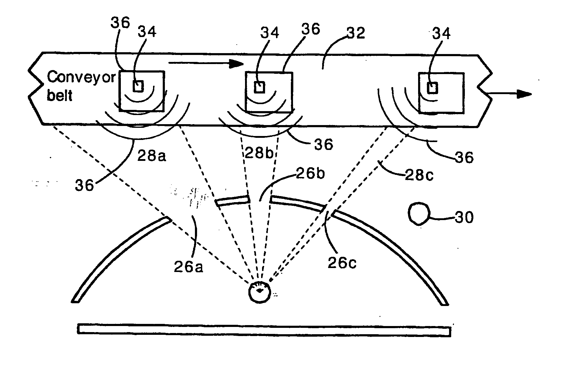
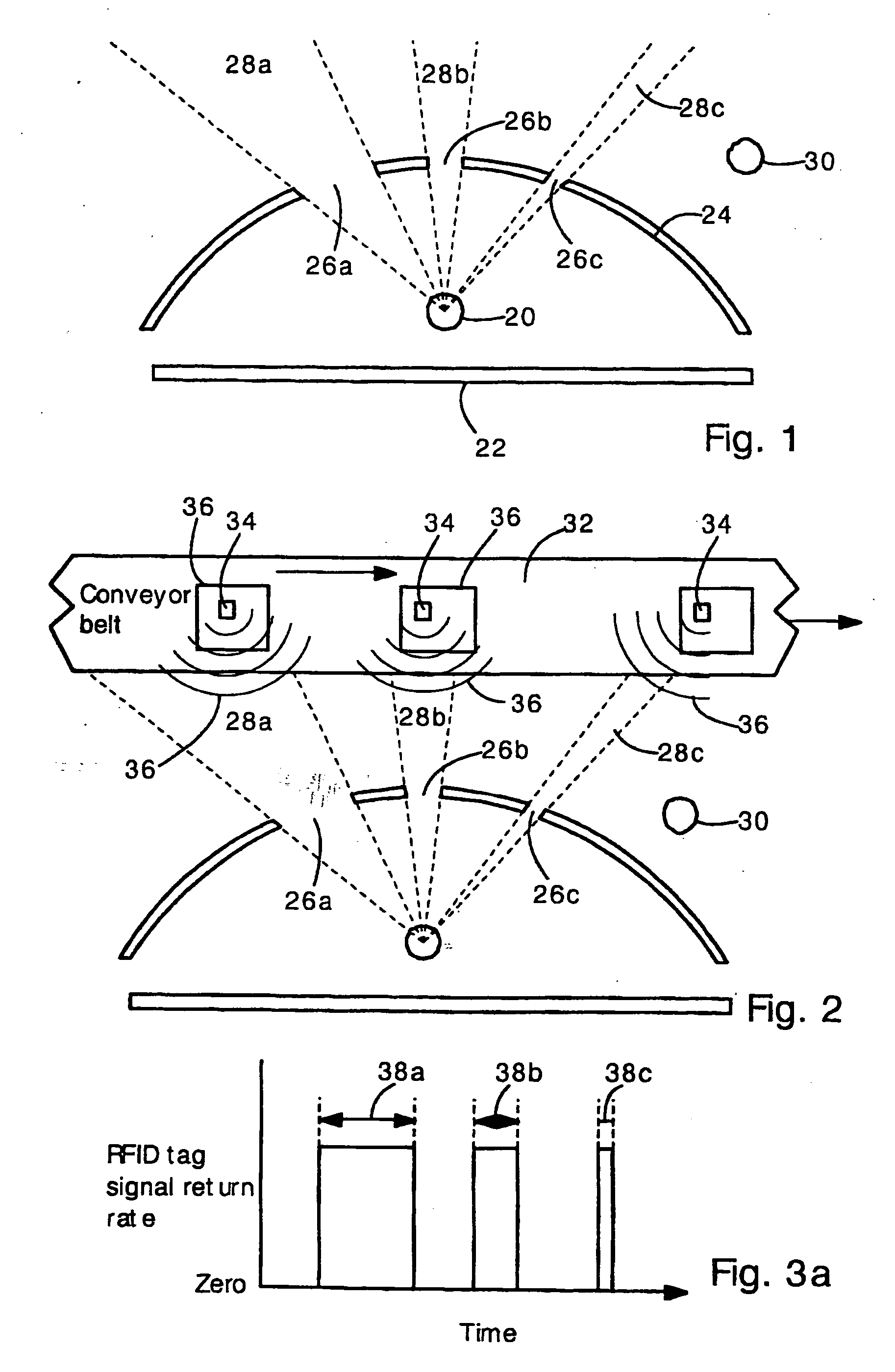
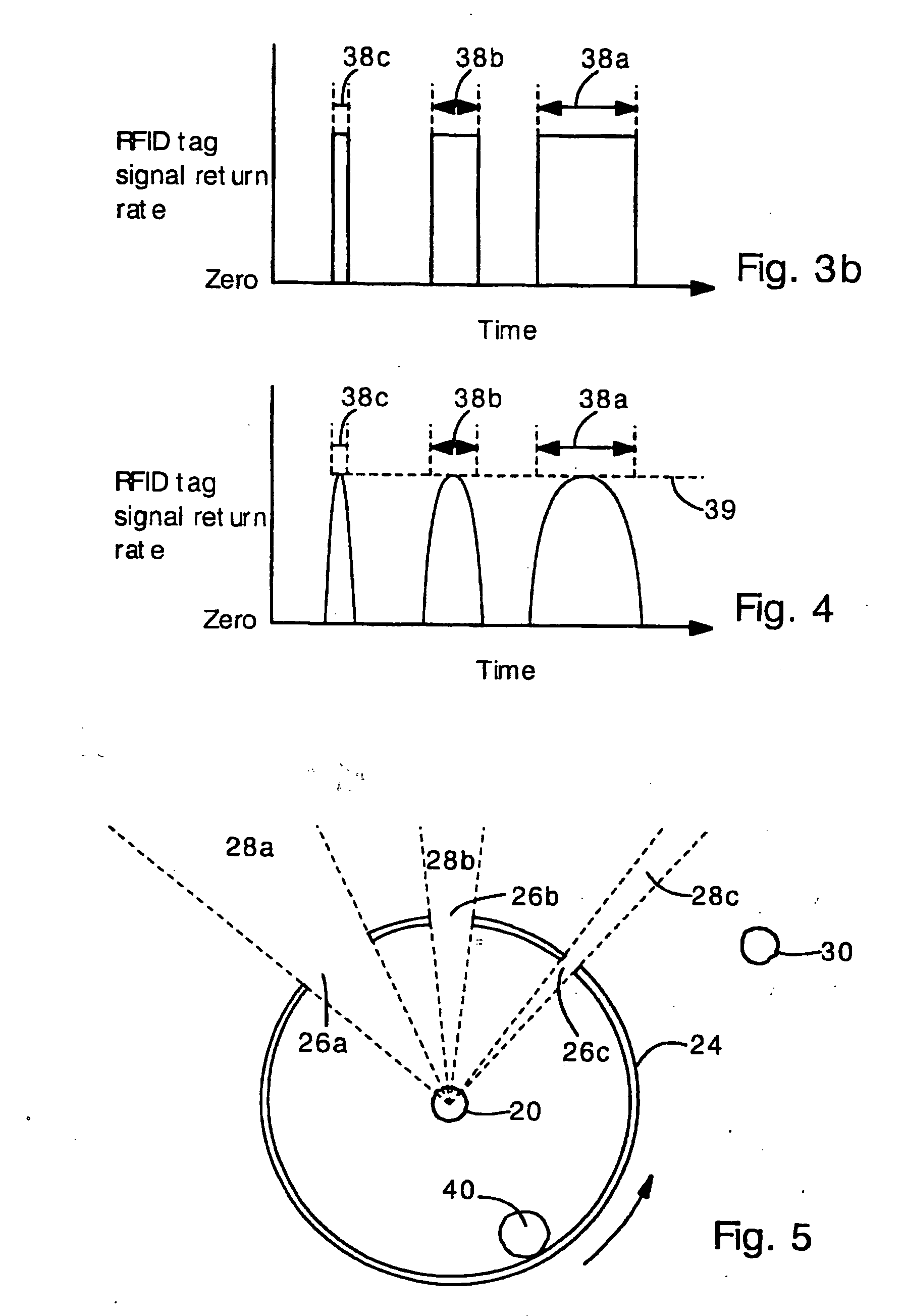
[0024] The present invention provides an antenna structure and method for determining the location of a radio frequency identification (RFID) tag. The antenna structure comprises a conventional wide-angle antenna (e.g., a dipole antenna) surrounded by a non-uniform attenuator (e.g., sheet metal plate with holes). The attenuator may completely block or partially block the RFID tag signal in certain directions. The attenuator has windows (openings) that allow the RFID tag signal to pass through the attenuator. The antenna can detect the RFID tag signal only when the RFID tag is aligned with a window. In this way, the antenna can determine that the tag is located at one or one of several angular positions aligned with a window. If the RFID tag is traveling along a known pathway (e.g., along a road, train track, part carrying track, or conveyor belt) then the RFID tag position can be further defined. If the RFID tag passes in front of several windows having different sizes and angular p...


PUM


Abstract

An antenna structure capable of determining the direction of a radiofrequency identification (RFID) tag includes a wide-angle antenna disposed within an attenuator that has regions of low attenuation. The attenuator may include a metal plate with holes. In this case, the antenna only detects RFID tags that are aligned with a hole, and hence the direction of the RFID tag is detected. Multiple holes of different sizes can be provided. In this case, if the RFID tag is moving, the direction and speed of movement can be determined from the duration of received RFID signals. For example, a long period of RFID tag signal reception indicates that the tag passed in front of a large hole in the attenuator. The present invention is particularly well suited for use with conveyor belts and in applications where RFID tags move along known paths.

Description

FIELD OF THE INVENTION [0001] The present invention relates generally to methods for locating radio frequency identification (RFID) tags. More specifically, the present invention relates to an antenna structure with shielding elements that allow determination of the direction to the RFID tag. BACKGROUND OF THE INVENTION [0002] Radio frequency identification (RFID) tags are small electronic circuits that provide identifying information in a manner akin to barcodes. RFID tags are becoming ubiquitous in many manufacturing, shipping and warehousing applications. [0003] In operation, RFID tags are queried by an electromagnetic RF pulse of a certain frequency. After reception of the RF pulse, the RFID tag responds with an RF pulse containing encoded information. Typically, the encoded information identifies an object or merchandise associated with the RFID tag. [0004] In many applications, it is important to determine the location or direction of motion of an RFID tag. For example, if an ...

Claims


Application Information

Patent Timeline
IPC IPC(8): G08B13/14
CPCG01S13/58G01S13/765G06K7/10435G06K7/10336G06K7/10079
Inventor MULLINS, PHILIP KENDAL
Owner IBM CORP
Why Eureka
Try Eureka