Cable splicing operation platform

An operation platform and optical cable splice box technology, which is applied in the coupling of optical waveguides, can solve the problems of low welding quality, low efficiency, and poor stability, and achieve the effects of improving efficiency, ensuring quality, and quickly installing

Inactive Publication Date: 2013-09-11
STATE GRID CORP OF CHINA +1
View PDF3 Cites 5 Cited by
  • Summary
  • Abstract
  • Description
  • Claims
  • Application Information

AI Technical Summary

Problems solved by technology

[0003] Aiming at the common problems of poor stability, low welding quality and low efficiency in the existing outdoor optical cable welding, the present invention provides an optical cable welding operation platform to ensure the safety of optical cable cutover, improve the reliability rate of optical cable welding and the quality and efficiency of optical cable welding

Method used


Image

  • Cable splicing operation platform
  • Cable splicing operation platform
  • Cable splicing operation platform

Examples


Embodiment Construction

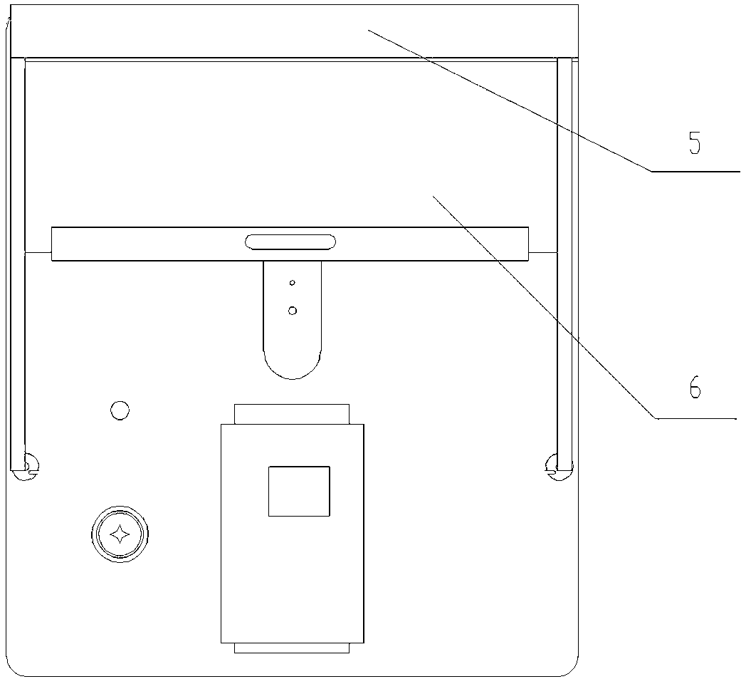
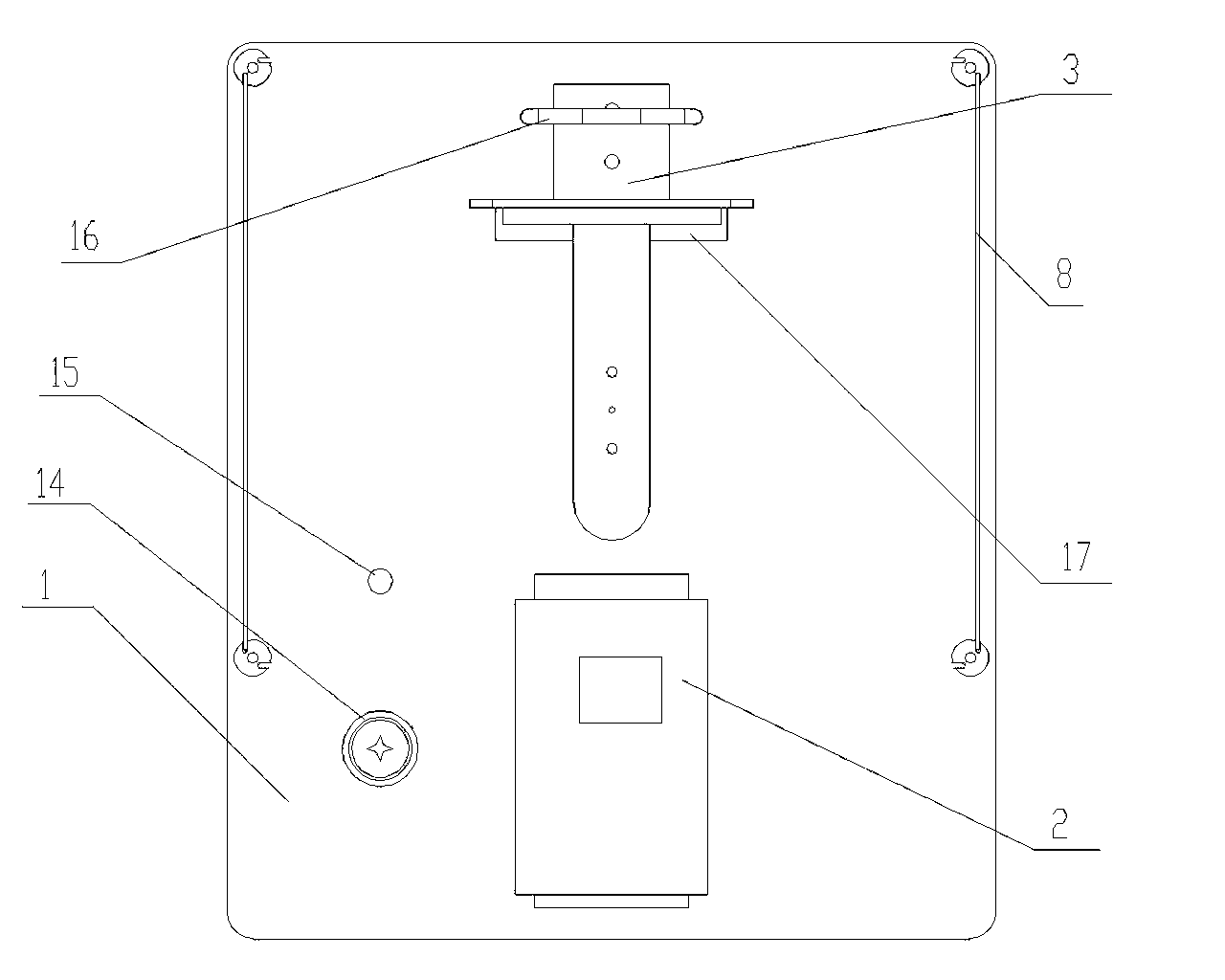
[0024] combine figure 1 , figure 2 , image 3 , Figure 4 , Figure 5 and Figure 6 As shown, the optical cable fusion operation platform provided by the present invention includes a workbench 1 with legs 11, and the two ends in the horizontal direction of the workbench are respectively provided with a groove 13 for placing a fusion splicer 2 and a fixed optical cable splice box 3 The U-shaped clamping plate 16 of the U-shaped clamping plate 16 offers a rectangular fixing groove 17 that cooperates with the optical cable splice box 3 disk parts on the inner side of the U-shaped clamping plate 16, and a groove 14 for placing a spirit level and an umbrella hole 15 are also provided on the workbench surface. . The optical cable entrance limit of workbench 1 is provided with rear windshield 4, and adjacent two sides are provided with side windshield 8, and the bottom edge of rear windshield 4 has the notch that passes through optical cable, see Figure 8 , Figure 9 shown. ...


PUM


Abstract

The invention discloses a cable splicing operation platform comprising a platform body with support legs. Two ends, in the horizontal direction, of the top of the platform body are provided with a groove for accommodating a splicer and a U-shaped clamping board for fixing a cable joint box. A rectangular fixing groove is formed at the inner top of the U-shaped clamping board and matches with a disc part of the cable joint box. Wind boards are arranged at a cable inlet of the platform body and on adjacent two sides. By the aid of the cable splicing operation platform, splicing workers can set up and place splicing equipment conveniently under various conditions, the cable splicer, an OPGW (optical fiber composite overhead ground wire) cable and the joint box can be fixed, cable breakage or core breakage due being mistakenly hit by external forces can be avoided, safe cutting and splicing of the cables can be guaranteed, the reliability rate, quality and efficiency of cable splicing can be increased, and quality and efficiency of cable splicing can be improved. The cable splicing operation platform can be assembled rapidly, and is adaptable to terrains, convenient to operate and carry, reasonable in structure, light in weight, durable and consistent to splicing specifications.

Description

technical field [0001] The invention relates to the technical field of optical cable welding, in particular to an operating platform for outdoor optical cable welding. Background technique [0002] With the advancement of smart grid construction, the importance of power communication has become increasingly prominent. As the main physical platform for information transmission, optical cables transmit important information such as relay protection, information collection and control of electrical equipment, two-way interactive information of users, and real-time information of electric meters. As the technical support for the safe, stable and high-quality operation of the power grid, the communication optical network is playing an increasingly important role. When performing line optical cable cutover, especially OPGW optical cable, most of them are in 110KV and 220KV lines. The location of optical cable cutover is uneven and the conditions are poor. The on-site staff and ve...

Claims


Application Information

Patent Timeline
Patent Type & Authority Applications(China)
IPC IPC(8): G02B6/255
Inventor 张友许长林马曙光葛乃胜李敏易飞杨志千高伟
Owner STATE GRID CORP OF CHINA
Why Eureka
Try Eureka