Automatic monitor sliding system

a monitor and automatic technology, applied in the direction of instruments, electrical apparatus casings/cabinets/drawers, instruments, etc., can solve the problems of dust, water permeation, mistouching input, etc., to prevent dust, water permeation, and mistouching input, and high sliding radian

a monitor and automatic technology, applied in the direction of instruments, electrical apparatus casings/cabinets/drawers, instruments, etc., can solve the problems of dust, water permeation, mistouching input, etc., to prevent dust, water permeation, and mistouching input, and high sliding radian

US20070030647A1Inactive Publication Date: 2007-02-08BCOM ELECTRONICS

Image

  • Automatic monitor sliding system
  • Automatic monitor sliding system
  • Automatic monitor sliding system

Examples


Embodiment Construction

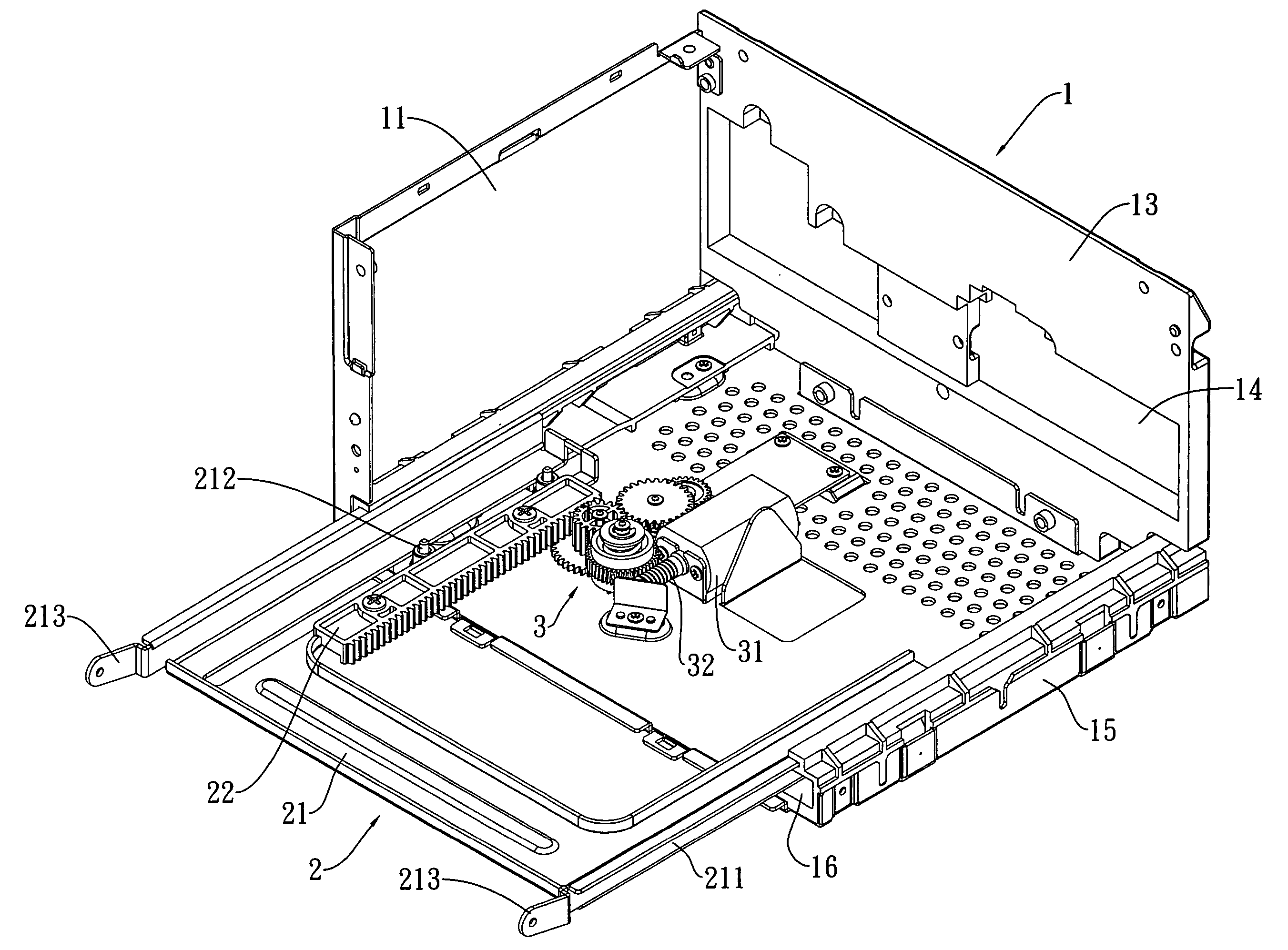
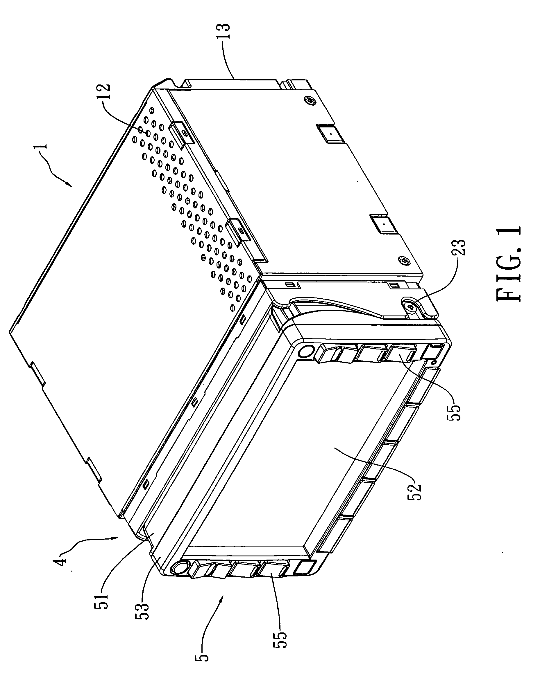
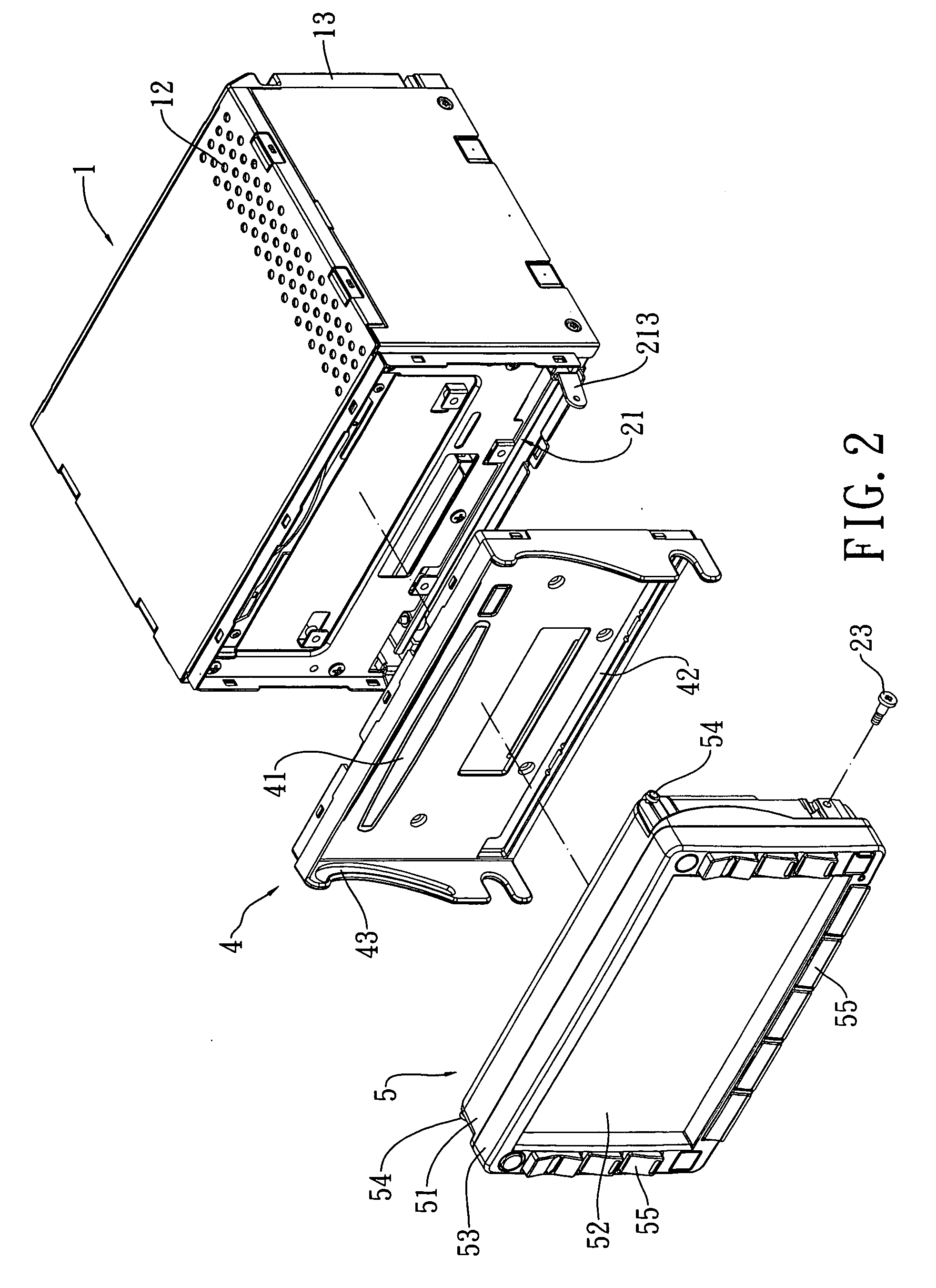
[0021] Referring to FIG. 1 to FIG. 3, an automatic monitor sliding system of the present invention is shown. The automatic monitor sliding system comprises a machine case 1, a slidable structure 2, a monitor mounting plate 4, and a monitor structure 5.

[0022] The machine case 1 comprises: a reception chamber 11 on which components can be mounted for working; a plurality of heat-dispersing holes 12 on a top case and a bottom case for dispersion of the heat from the inside components to prevent excessive heat from causing the inside components unworkable; a heat-dispersing plate 13 having a transmission interface 14 to which a related signal source is connected for signal transmission; a base 15; and a guide trench 16 mounted on each side of the base 15. The guide trenches 16 are designed in the form of a bar to match the sliding distance.

[0023] The slidable structure 2 is mounted inside the machine case 1 and mounted on the interior lower portion of the machine case 1. The slidable ...


PUM


Abstract

An automatic monitor sliding system comprises a machine case, a slidable structure, a monitor mounting plate, and a monitor structure. The slidable structure is mounted inside a reception chamber of the machine case. The monitor mounting plate is mounted in front of the machine case. The monitor structure is mounted in front of the monitor mounting plate. As a result, the slidable structure slides the monitor structure forward to slant the monitor structure downward for facilitating the user to insert and retrieve the audio-visual disk. Consequently, the automatic monitor sliding system provides the functions of protecting machine, preventing dust, water permeation, and mistouch input, and providing high sliding radian.

Description

FIELD OF THE INVENTION [0001] The present invention is related to an automatic monitor sliding system, and more particularly to an automatic monitor sliding system that slides and slants the monitor structure downward by the slidable structure to be suitable for any kind of audio-visual device or the like. The slidable structure is mounted inside a reception chamber of the machine case. The monitor mounting plate is mounted in front of the machine case. The monitor structure is mounted in front of the monitor mounting plate. As a result, the slidable structure slides the monitor structure forward to slant the monitor structure downward for facilitating the user to insert and retrieve the audio-visual disk. Consequently, the automatic monitor sliding system provides the functions of protecting machine, preventing dust, water permeation, and mistouch input, and providing high sliding radian. BACKGROUND OF THE INVENTION [0002] Nowadays the current workers always take two days off a wee...

Claims


Application Information

Patent Timeline
08 Feb 2007
Publication
US20070030647A1
IPC
G06F1/20; F16H59/00
CPC
B60R11/0235; B60R2011/0082; B60R2011/0085; B60R2011/0092; F16H1/16; Y10T74/19251; G06F1/18; G11B17/051
Inventors
CHEN, JIAN-CHENG; SHIH, CHUN-CHANG