Arcuate guide apparatus and method for conveyor(s)

Inactive Publication Date: 2007-02-08
KINZER DWIGHT ERIC
View PDF10 Cites 3 Cited by
  • Summary
  • Abstract
  • Description
  • Claims
  • Application Information

AI Technical Summary

Benefits of technology

[0055] (g) to provide a conveying system

Problems solved by technology

A significant cost in designing feed mills, grain elevators, seed conditioning plants, industrial bulk material handling, storage, and processing facilities, and the like is the conveying system.
Such equipment can be costly, not only in actual price, but also in terms of maintenance and energy requirements.
Cross-contamination is the inadvertent intermingling of one product with another.
These intermediate discharge gates can often be sources of cross-contamination since they are hard to cleanout.
Filling into or recovering material from an array of bins using conventional methods often requires many linear-meters of conveying equipment, multiple intermediate discharge gates for distribution (which are sources of cross-contamination), and a relatively large amount of energy to run the equipment.
Cross-contamination issues have become prevalent in recent years due to several factors, such as increased demand for identity preserved traits, the development of transgenic organisms, and food security in general.
Thus, the more conveyors that are used to distribute or reclaim materials, the more opportunity for cross-contamination.
Limitations of this arrangement include the following: (1) the use of steep incline screw conveyors creates cross-contamination issues, since they are not easily completely cleaned of product; (2) rotation is limited by product receiving area requirements; (3) multiple conveyors are needed to reach outlying bins; (4) the design requires a relatively large footprint, which may be limiting in many facilities; and (5) the rotational axis is controlled by a center support.
In Hozak's design, the system once again requires a relatively large footprint, and as the height of the bins increase, so does the floor space requirement.
This system also requires significant space above the bins.
This system has an extendable auger at the end of a boom that pivots around a mast, and is limited to filling only one arc of receptacles.
This system also requires a large footprint, and cleanout is relatively difficult.
Sawby's apparatus would not be practical for multiple rows of bins, or for conveyors with high volumes that would create heavy loads onto the boom and mast.
The conveying system disclosed by Sackett is functionally limited to square or rectangular bins, and it requires multiple conveyors.
Stafford and Elder's device requires a large footprint and is limited to one type of structure.
The wheels rest upon a track and do not provide significant guidance.
The Goeke system has one wheel trolleys resting upon a track and does not have a mechanism at a central axis but its conveyor does not have any means of staying on the track if it is subjected to upward, uneven downward, lateral, or radial forces.
Goeke's apparatus would have difficulty with a cantilevered conveyor or an inclined conveyor.
If a foreign object were on the track of this system, the wheels would have a tendency to jump over the object and depart from the track, rather than being blocked and coming to a stop.
The trolley system is not designed to provide any contribution beyond providing a linear guidance and weight support.
The one-wheel trolley system does not provide for significant guidance but is instead primarily used for supporting the weight.
c. difficult to control long conveyors from a central mechanism.
Hessling's apparatus would not be suitable for multiple concentric tracks, tall silos, long-heavy-high-volume conveying systems, or systems that require more than 180° of rotational capability.
The remaining relevant prior art relies on a simple trolley system that does not provide significant guidance to the conveyor when subjected to uneven, lateral, or radial forces.
As far as I am aware, there is not a track-and-trolley conveyor guidance system designed to withstand uneven, lateral, or radial loads without a central support mechanism while maintaining guidance to the conveyor.
The problem with conventional distribution conveyors is that the intermediate discharge gates tend to have carryover problems that can cause potential cross-contamination.
Also, intermediate discharge gates on a conventional conveyor tend to seal imperfectly with the conveyor trough, creating further cross contamination potential.
Material moving along long lengths of down-spouting can reach relatively high speeds, and thus can land harshly within a bin.
Such impacts can significantly lower product quality, and so, in many cases, down-spouting is undesirable.
There are also cross-contamination issues with the conventional methods of directing grain or ingredient flow to one of multiple downspouts.
In summary, the following are typical disadvantages of conventional conveying or spouting systems that are used to fill a plurality of bins: (a) multiple long conveyors are usually needed, requiring many linear meters of conveyor, which increase cross-contamination risk and adds to energy and maintenance costs; (b) multiple discharge gates on the conveyor are often necessary for distribution, which increases risk of cross-contamination; and (c) some of the prior-art apparatuses have inherent cross-contamination or commingling problems.
In summary, the following are typical disadvantages of conventional trolley assisted conveying systems to fill a bin residing within a cluster of bins: (a) a central shaft or central support mechanism is usually required to maintain the center of axis; (b) existing trolley designs do not show mechanisms to withstand upward, downward, lateral, uneven, and / or radial forces, while maintaining desired guidance; (c) prior art systems do not confine movement to only the desired linear or radial path; (d) a central support device that can withstand substantial loads when supporting and / or controlling long and / or heavy conveyance systems might not be feasible with most storage silos; (e) a single wheel trolley assembly that only rests on a track cannot withstand upward, uneven downward, lateral, and / or radial forces; (f) many of the prior art systems increase the roof height requirements above the silos; (g) some of the cited prior art would only be practical with one type of conveyance such as a screw type conveyor and would not be suited for other types of mechanical conveyors; and (h) some of the prior art apparatuses have inherent cross-contamination or commingling flaws.
In summary, the following are typical disadvantages of conventional conveying systems to recover material from a plurality of bins: (a) many linear meters of conveyor are needed, which increases cross-contamination risk and adds to energy and maintenance costs; (b) some of the prior art apparatuses have inherent cross-contamination or commingling flaws; (d) conventional conveying systems may require a central shaft or mechanism to maintain an axis, support the conveyor, or to control the conveyor; and (e) conventional conveying systems have no mechanism to move a conveying device under storage bins and between storage bin support legs.

Method used


Image

  • Arcuate guide apparatus and method for conveyor(s)
  • Arcuate guide apparatus and method for conveyor(s)
  • Arcuate guide apparatus and method for conveyor(s)

Examples


Embodiment Construction

—FIGS. 1, 2A, AND 2B

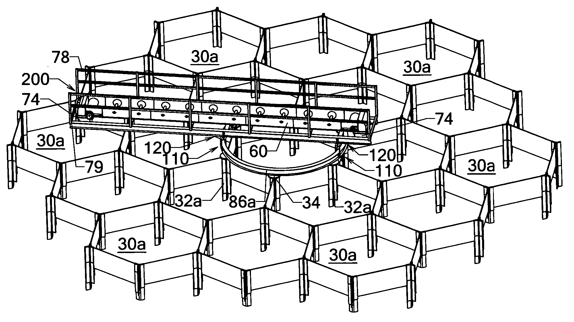
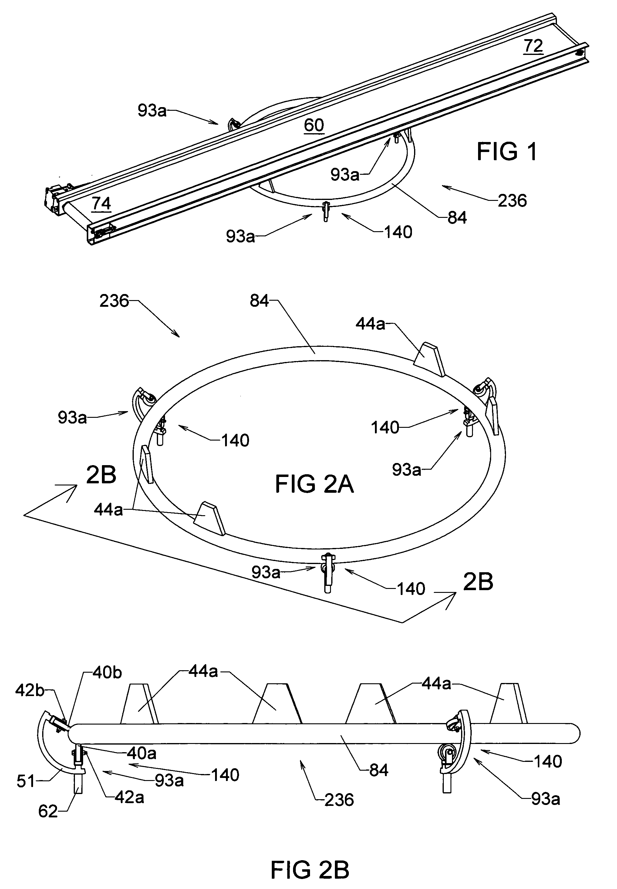
[0252] All of the of the prior art cited, whether with or without a central support and / or control mechanism, only uses a one-wheel trolley. The addition of a second wheel to a trolley that is a component of a multiple trolley guide assembly provides significant advantages to a track-and-trolley conveyor guidance system. FIG. 1 shows an apparatus of a track-and-trolley conveyor guidance system 236 that comprises a guide assembly 140 attached to a conveyor 60. System 236 is the simplest embodiment of this invention while providing all of the desired characteristics. System 236 guides conveyor 60 along the radial path of a track 84, as conveyor 60 is subjected to forces or loads associated and not associated with moving conveyor 60. System 236 can refer to a method or to an apparatus. System 236 can serve a plurality of bins, primarily for distributing material to the bins, and, to a limited degree, to claim material from the bins.

[0253]FIG. 2A is an isometric vie...


PUM


Abstract

An arcuate guide apparatus and method for collecting and moving material into or away from a selected bin (30a, 30b, 30c) that resides within an array of storage bins. The arcuate guide apparatus comprises three or more trolleys (90, 91, 92, 93, 94, 95a, 95b, 96, 97, 98, 99, 100, 101, 102, 103, 104, 105, 106, 107, 108) that move along at least one track (79, 80, 81, 82, 83, 84, 86a, 86b, 86c, 86d, 86e, 86f, 87a, 87b, 88a, 88b, 89) to create a guide assembly for a conveyor (60) or conveyor groups (67, 68, 69, 70). By moving the trolleys (90, 91, 92, 93, 94, 95a, 95b, 96, 97, 98, 99, 100, 101, 102, 103, 104, 105, 106, 107, 108) along the track (79, 80, 81, 82, 83, 84, 86a, 86b, 86c, 86d, 86e, 86f, 87a, 87b, 88a, 88b, 89), or track (79, 80, 81, 82, 83, 84, 86a, 86b, 86c, 86d, 86e, 86f, 87a, 87b, 88a, 88b, 89) along the trolleys (90, 91, 92, 93, 94, 95a, 95b, 96, 97, 98, 99, 100, 101, 102, 103, 104, 105, 106, 107, 108), the conveyor (60) or conveyor groups (67, 68, 69, 70) can distribute material to or reclaim material from a selected storage bin (30a, 30b, 30c) using minimal amount of linear meters of conveyance (60). The arcuate guide apparatus and method can have multiple layers of guide assemblies (110, 112, 114, 120, 122, 124, 126, 128, 130, 132, 134, 136, 138, 140, 142, 144, 146, 148, 150, 152, 154, 156, 158, 160, 162) to guide conveyor (60) or conveyor groups (67, 68, 69, 70). The arcuate guide apparatus and method can have the guide assemblies (110, 112, 114, 120, 122, 124, 126, 128, 130, 132, 134, 136, 138, 140, 142, 144, 146, 148, 150, 152, 154, 156, 158, 160, 162) combined in a wide variety of configurations that best suits a particular application.

Description

CROSS-REFERENCE TO RELATED APPLICATIONS [0001] This application is a divisional application of U.S. patent application Ser. No. 11 / 190,362, filed Jul. 27, 2005, which claims the benefit of continuation-in-part application of U.S. patent application Ser. No. 10 / 771,807, filed Feb. 03, 2004, which claims the benefit of U.S. Provisional Application Ser. No. 60 / 445,760, filed Feb. 05, 2003.FEDERALLY SPONSORED RESEARCH [0002] Not applicable SEQUENCE LISTING OR PROGRAM [0003] Not applicable BACKGROUND OF THE INVENTION [0004] 1. Field of the Invention [0005] This invention relates to track-and-trolley conveyor guidance systems, specifically to such systems that fill material into or recover material from a plurality of storage bins. [0006] 2. Discussion of Prior Art [0007] A significant cost in designing feed mills, grain elevators, seed conditioning plants, industrial bulk material handling, storage, and processing facilities, and the like is the conveying system. These facilities general...

Claims


Application Information

Patent Timeline
IPC IPC(8): B65G65/00B65D88/02B65G41/00B65G65/32B65G69/04
CPCB65D88/022B65G15/24B65G21/12B65G2201/042B65G69/0408B65G69/0416B65G41/005
Inventor KINZER, DWIGHT ERIC
Owner KINZER DWIGHT ERIC
Why Eureka
Try Eureka