High Voltage Nanosecond Pulse Generator Using Fast Recovery Diodes for Cell Electro-manipulation

a nanosecond pulse generator and fast recovery technology, applied in pulse manipulation, pulse technique, biomass after-treatment, etc., can solve the problems of only a low repetition rate, large physical size, cell death, etc., and achieve the effect of reducing the number of cycles

Active Publication Date: 2007-02-08
UNIV OF SOUTHERN CALIFORNIA
View PDF11 Cites 28 Cited by
  • Summary
  • Abstract
  • Description
  • Claims
  • Application Information

AI Technical Summary

Benefits of technology

[0025] The pulse generator may include a diode that is configured to operate as an opening switch and that saturates in less than 100 nanoseconds.

Problems solved by technology

Permanent openings may result in cell death.
However, they may be physically large and have only a low repetition rate.
They may also have only a relatively short lifetime, and provide erratic pulses with a large amount of jitter.
However, MOSFET switched capacitors may not be able to generate pulses that are narrower than 15-20 ns.
This may be due to complications of MOSFET driving circuits and inherent limitations of many MOSFET devices.

Method used


Image

  • High Voltage Nanosecond Pulse Generator Using Fast Recovery Diodes for Cell Electro-manipulation
  • High Voltage Nanosecond Pulse Generator Using Fast Recovery Diodes for Cell Electro-manipulation
  • High Voltage Nanosecond Pulse Generator Using Fast Recovery Diodes for Cell Electro-manipulation

Examples


Embodiment Construction

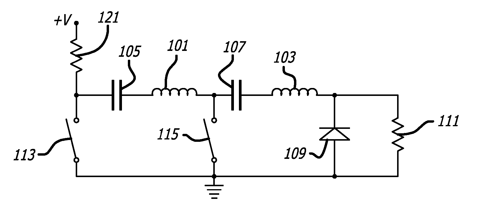
[0036]FIG. 1 is a simplified diode pulse generator.

[0037] As shown in FIG. 1, the diode pulse generator may include a tank circuit consisting of inductances 101 and 103 and capacitances 105 and 107. The tank circuit may be connected in series with a diode 109 across which a load to be driven 111 may be connected. The pulse generator may include a switching system, such as switches 113 and 115, which may be electronic. A voltage supply 119 may be connected to the diode pulse generator through a resistance 121.

[0038] Before the beginning of a pulse cycle, the switch 113 may be open and the switch 115 may be closed. This may cause the capacitance 105 to fully charge and the capacitance 107 to fully discharge.

[0039] At the beginning of the pulse cycle, the switch 113 may be closed and the switch 115 may be opened. This may cause charge to transfer from the capacitance 105 to the capacitance 107. During this transfer, the current through the tank circuit may rise and fall in approxima...


PUM

PropertyMeasurementUnit
frequencyaaaaaaaaaa
impedanceaaaaaaaaaa
impedanceaaaaaaaaaa

Abstract

A pulse generator circuit may include a diode configured to operate as an opening switch, a tank circuit in series with the diode having an admittance that is switchable from a first value to a second value that is different from the first value, and a switching system configured to cause the tank circuit to switch between the first value and the second value. The diode may saturate in less than 100 nanoseconds. A saturable core transformer may operate as a switch that controls the opening of the diode. The pulse generator may generate a plurality of pulses, each having a length of no more than 3 nanoseconds and an amplitude of at least 1 kilovolt. Electrodes may be connected to the pulse generator to deliver the plurality of pulses to biological cells.

Description

CROSS-REFERENCE TO RELATED APPLICATIONS [0001] This application is based upon and claims priority to U.S. Provisional Application Ser. No. 60 / 673,949, filed Apr. 22, 2005, attorney docket no. 28080-163, entitled “Nanosecond Pulse Generator for Cell-Electro-Manipulation,” the entire content of which is incorporated herein by reference.STATEMENT REGARDING FEDERALLY SPONSORED RESEARCH [0002] This invention was made with government support under the U.S. Air Force Office of Scientific Research Grant Nos. F29620-01-1-0387 and F49620-01-1-0495 and U.S. Army Research Office Grant No. DAAD 19-01-1-0698. The government may have certain rights in the invention.BACKGROUND [0003] 1. Field [0004] This application relates to pulse generators and, more particularly, to pulse generators that may be used for electroperturbation of biological cells. [0005] 2. Description of Related Art [0006] Ultra-short, high-field strength electronic pulses may be used in the electroperturbation of biological cells...

Claims


Application Information

Patent Timeline
Patent Type & Authority Applications(United States)
IPC IPC(8): C12M1/00
CPCC12M35/02H03K17/74H03K5/12H03K3/57
Inventor KUTHI, ANDRASGUNDERSEN, MARTIN A.
Owner UNIV OF SOUTHERN CALIFORNIA
Why Eureka
Try Eureka