

Visual sports training apparatus and method
- Summary
- Abstract
- Description
- Claims
- Application Information
AI Technical Summary
Benefits of technology
Problems solved by technology
Method used
Image

Examples
Embodiment Construction
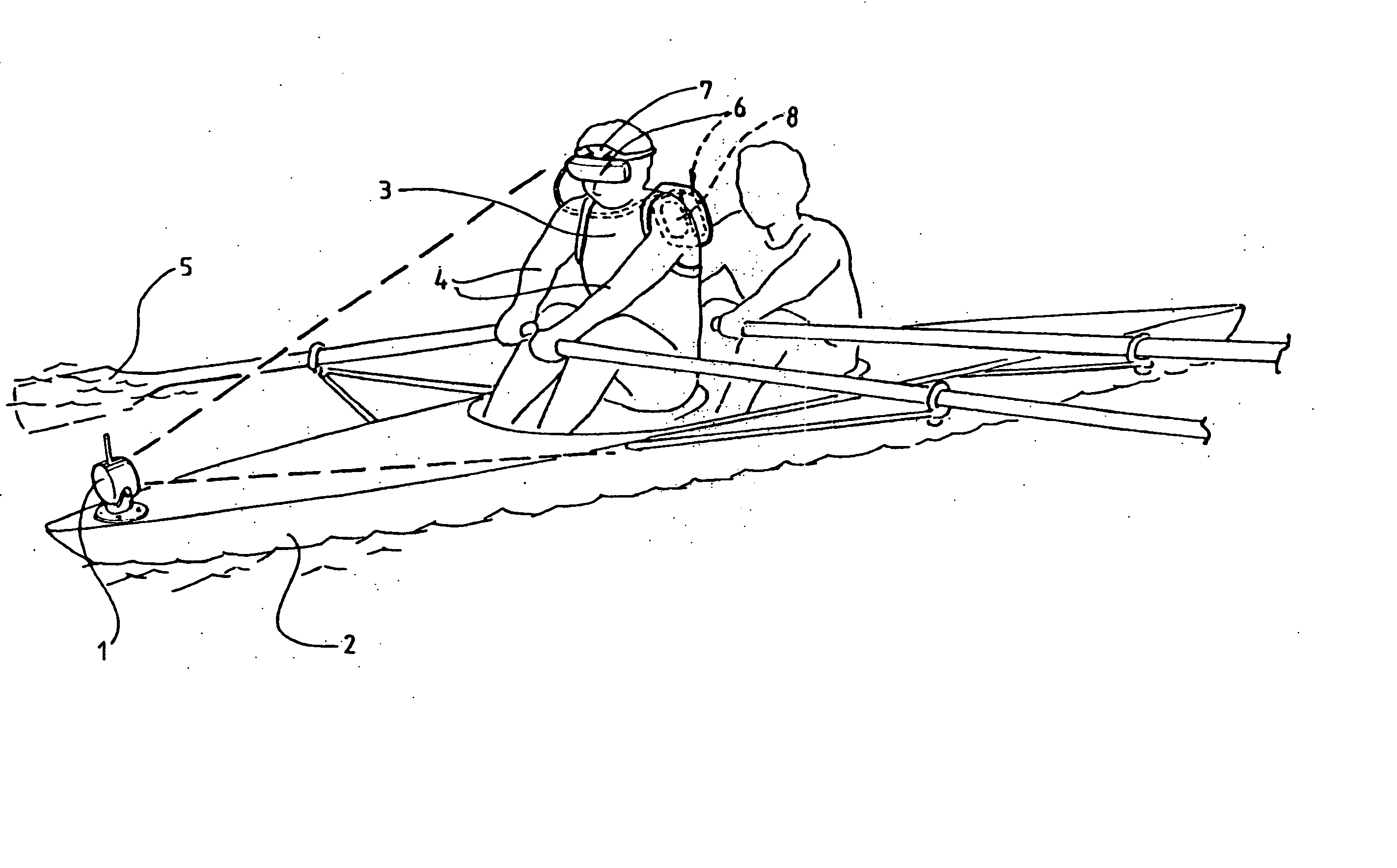
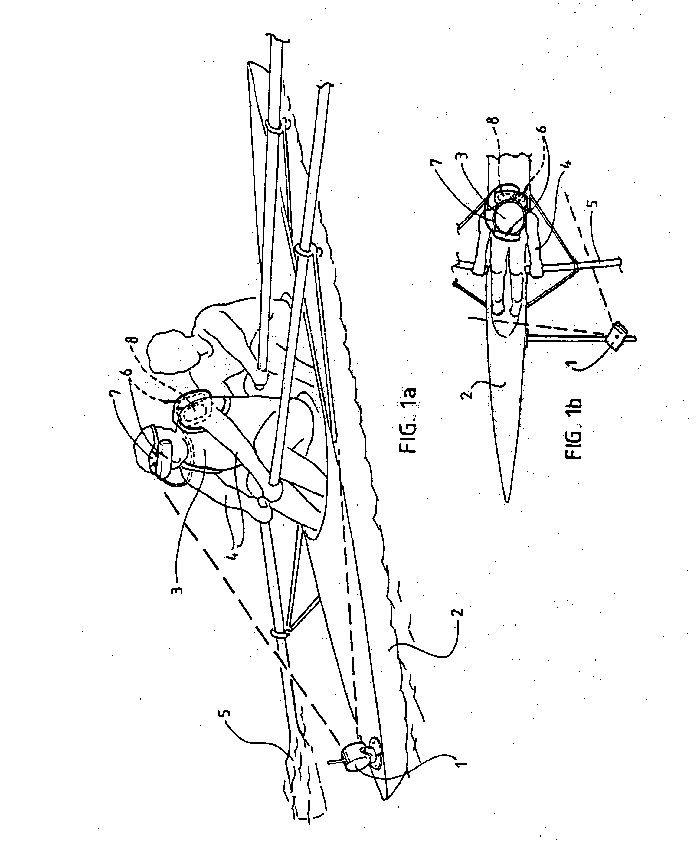
[0039] The invention will now be described with reference to one particularly preferred embodiment with the invention being generally applied to the sport of rowing as shown in the accompanying figures as follows:
[0040]FIG. 1 shows a perspective and top view of a row boat equipped with the system of the invention.
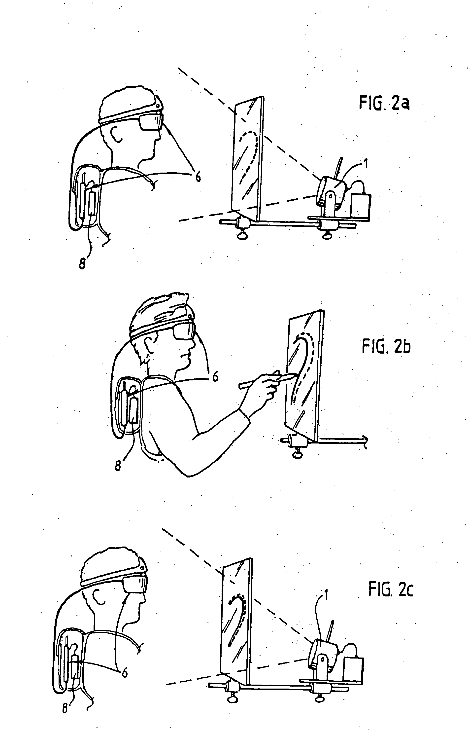
[0041]FIG. 2 shows the system used in a non sport application for video mixing.
[0042]FIG. 3 shows a row boat where the rower is monitored and coached by an observer.
[0043]FIG. 4 shows the system applied to the sport of golf.
[0044]FIG. 5 shows the system used to provide remote visual access for a user.
[0045]FIG. 6 shows the components of the system.
[0046] Referring firstly to the schematic representation shown in FIG. 1, the invention provides a system and apparatus whereby a user, in this case, the rower is able to access real time video monitoring and images of their own movements as they row during the actual execution of this activity.
[0047] The system of the inve...
PUM
 Abstract
Description
Claims
Application Information