Supercharge Your Innovation With Domain-Expert AI Agents!

Medical cutting and/or holding instrument

a technology for holding instruments and medical instruments, applied in the field of medical cutting and/or holding instruments, can solve the problems of suited for endoscopic surgery, difficult assembly and disassembly, and high production cost of this type of medical instruments, and achieve the effect of avoiding accidental dissolution of coupling and folding easily and quickly

Inactive Publication Date: 2007-02-08
KARL STORZ GMBH & CO KG
View PDF9 Cites 8 Cited by
  • Summary
  • Abstract
  • Description
  • Claims
  • Application Information

AI Technical Summary

Benefits of technology

[0009] Because of the invention's coupling of the push-pull rod with play on both ends, it is possible that the rotation of the jaw member causes exclusively an axial sliding of the push-pull rod inside the guide channel of the shaft by means of an actuation of the rotatable gripping member of the handle. The play in coupling in a direction essentially perpendicular to the direction of motion of the push-pull rod makes it possible for the coupling points of the connected components running in each case on an arched course to follow just these arched tracks, but without at the same time causing a vertical mounting of the push-pull rod. A medical cutting and / or holding instrument of this design can also be inserted without problems into a narrow trocar sleeve and is thus suited for use in endoscopic surgery.
[0011] To simplify the coupling of the push-pull rod with the rotatable gripping member, it is further proposed with the invention that the distal-end longitudinal hole is configured as an open locking groove, which allows the push-pull rod to be hooked onto and unhooked again from the coupling with the gripping member in simple manner.
[0012] According to a first embodiment of the invention for configuring the coupling mechanism for dissolubly connecting the push-pull rod with the rotatable gripping member, it is proposed that this coupling mechanism is configured as a screw-in connection. The configuration of a screw-in connection constitutes a method of coupling between two components that is especially simple to produce and to operate.
[0014] According to a second embodiment of the invention for configuring the mechanism for dissolubly connecting the push-pull rod with the rotatable gripping member, it is proposed that the coupling mechanism for dissolubly connecting the push-pull rod with the rotatable gripping member takes the form of a pin-slot control, which includes a coupling rod positioned on the push-pull rod or on the stem end of the rotatable gripping member and an open catch groove configured in the other respective component for inserting and guiding the coupling rod. Because of the configuration of the distal-end longitudinal hole as an open catching groove, the push-pull rod can be folded easily and quickly out of the guide groove of the shaft for cleaning purposes.

Problems solved by technology

These structural features, which allow the medical instrument to be broken down into at least three parts—that is, the hollow tubular shaft, the push-pull rod, and the handle—make the production of this type of medical instrument more costly and make them difficult to assemble and disassemble.
The disadvantage of this known construction, however, is that at least the coupling of the push-pull rod with the rotatable jaw member of the tool causes a vertical mounting of the push-pull rod perpendicular to the direction of motion of the push-pull rod when the push-pull rod rotates the jaw member between the closed and open positions.
Because of this vertical mounting, in which the push-pull rod extends outside the guide groove of the shaft, a medical instrument of this type is not suited for use in endoscopic surgery, because it can result in jamming inside the trocar sleeve.

Method used


Image

  • Medical cutting and/or holding instrument
  • Medical cutting and/or holding instrument
  • Medical cutting and/or holding instrument

Examples


first embodiment

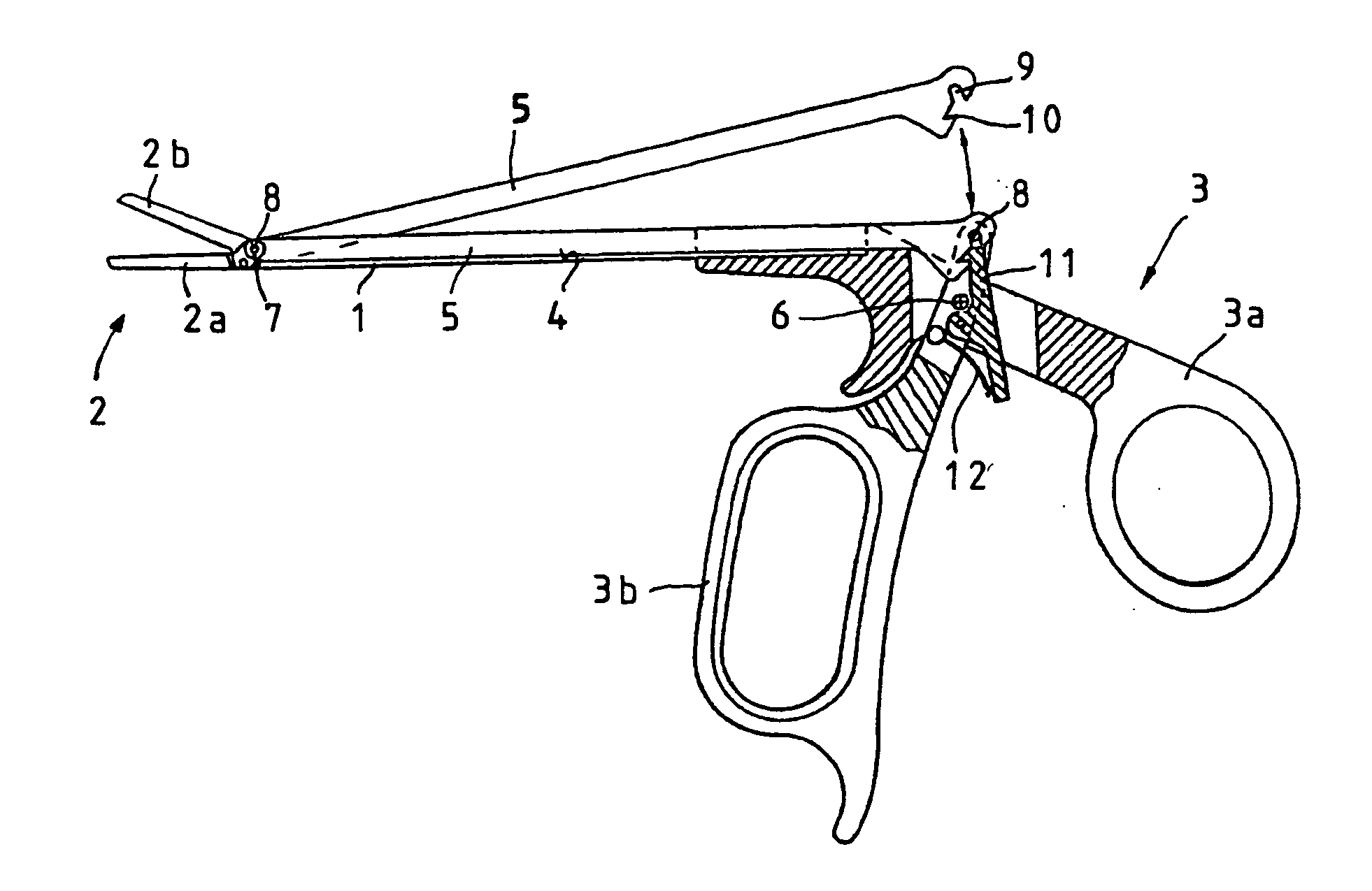
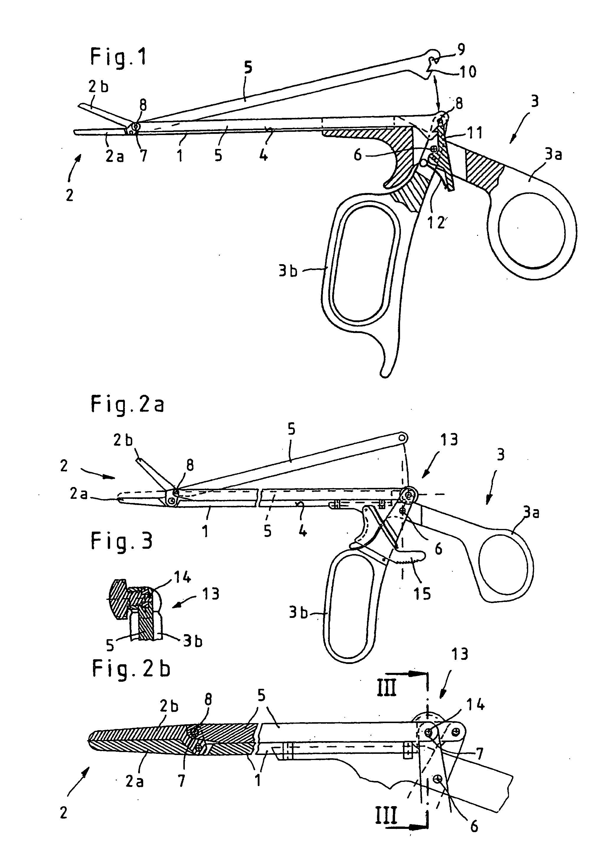
[0038] In the first embodiment, shown in FIG. 1, the coupling mechanism for dissolubly connecting the push-pull rod 5 with the rotatable gripping member 3b is configured as a pin-slot control, which includes a coupling rod 8 mounted on the stem end of the rotatable gripping member 3b and an open catch groove 9 configured on the proximal end of the push-pull rod 4 for inserting and guiding the coupling rod 8.

[0039] The illustration shows the push-pull rod 5 first in the assembly and cleaning position rotated upward out of the guide groove 4 of the shaft 1 and then in the working position coupled with the rotatable gripping member 3b.

[0040] To secure the push-pull rod 5 in the coupled working position and to prevent accidental uncoupling, the push-pull rod 5 in the illustrated embodiment can be fixed in the coupled position by means of a catching element 11 that engages in a catch slot, so that the catching element 11 is pre-tensioned by a spring element 12 in the direction of the ca...

second embodiment

[0042] In the second embodiment, shown in FIGS. 2a to3, the coupling mechanism for dissolubly connecting the push-pull rod 5 with the rotatable gripping member 3b is configured as a screw-in connection 13. For the configuration of the screw-in connection 13, the stem end of the rotatable gripping member 3b is configured in forked shape for insertion of the push-pull rod 5 and a threaded socket is configured in the push-pull rod 5 for inserting a threaded stud 14 of the screw-in connection 13. In the two fork-shaped ends of the rotatable gripping member 3b, corresponding longitudinal holes 7 are provided for inserting and guiding the threaded stud 14, as can be seen in particular from FIGS. 2b and 3.

[0043] As also to be seen from FIG. 2a, the rotatable gripping member 3b of the handle 3 can be fixed by a preferably spring-loaded stopping device 15 in the rotated position with respect to the rigid gripping member 3a.

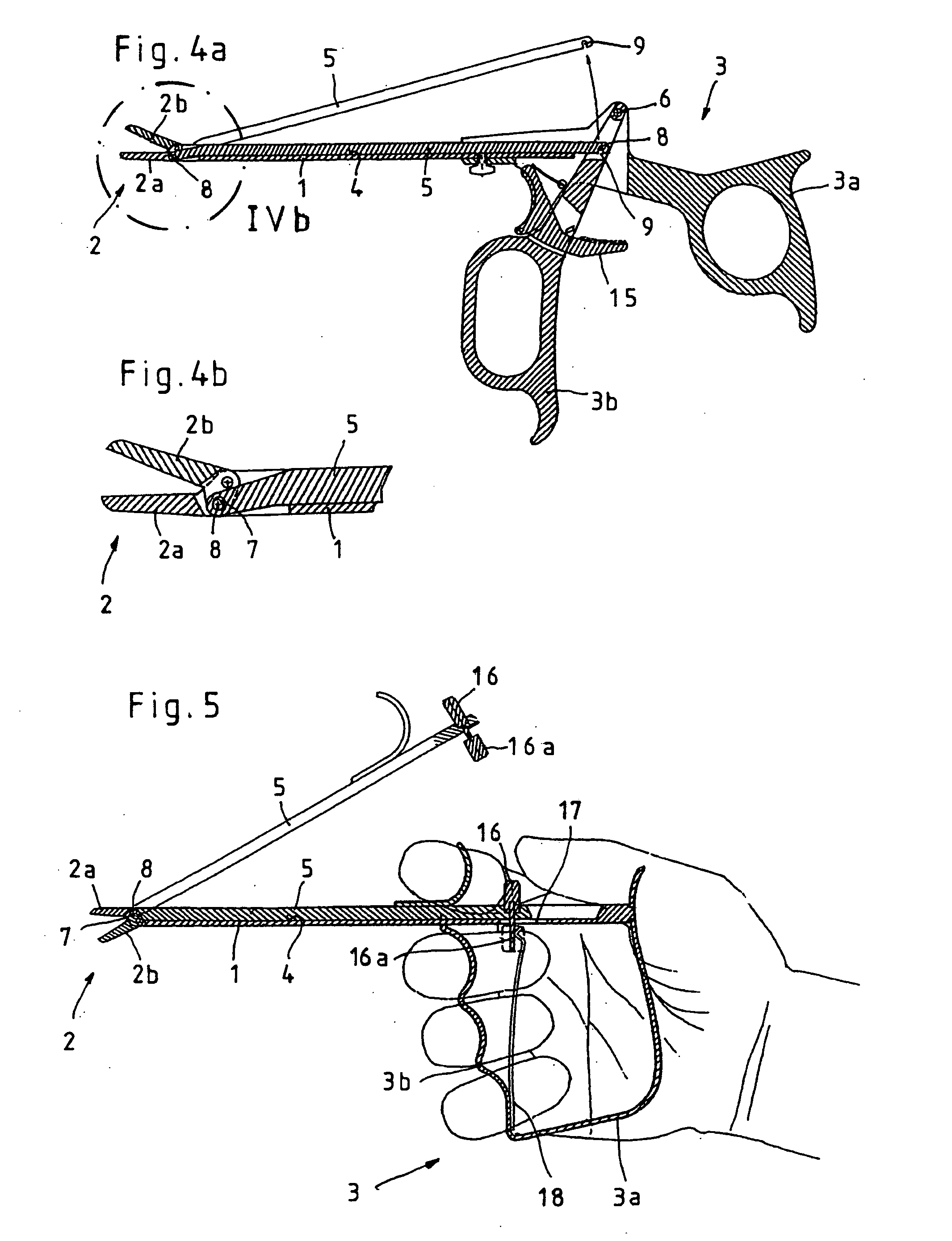
[0044] In the third embodiment, shown in FIGS. 4a and 4b, the coupli...

fourth embodiment

[0045] The fourth embodiment, illustrated in FIG. 5, finally, shows a medical cutting and / or holding instrument with an axially slidable gripping member 3b. Because in this configuration the proximal-end mounting point of the push-pull rod 5 is non-problematic because of the axial slidability of the gripping member 3b, it is sufficient that the push-pull rod 5 on the distal end is coupled with the rotatable jaw member 2b with free play in a direction essentially perpendicular to the direction of motion of the push-pull rod 5, in order to prevent the push-pull rod 5 from being raised out of the guide groove 4 of the shaft 1.

[0046] In this configuration the coupling mechanism for dissolubly connecting the push-pull rod 5 with the slidable gripping member 3b is configured as a drive rod 16 directed essentially perpendicularly to the direction of motion of the push-pull rod 5, and this drive rod 16 is mounted on the push-pull rod 5 on one end and supports itself on the other end on the ...


PUM


Abstract

The invention relates to a medical cutting and / or holding instrument having a shaft, a handle consisting of two gripping members that is positioned on the proximal end of the shaft, and a push-pull rod mounted in a guide groove of the shaft to actuate a tool consisting of two jaw members that is positioned on the distal end of the shaft, such that for opening and closing the tool the push-pull rod can be coupled on the distal end with at least one rotatable jaw member of the tool and on the proximal end with a rotatable gripping member of the handle, and such that the push-pull rod and the rotatable gripping member can be dissolubly connected with one another by a coupling mechanism. To produce a medical cutting and / or holding instrument that can also be used for endoscopic purposes, it is proposed with the invention that the push-pull rod is coupled with the rotatable components both on the proximal and the distal ends with free play in a direction essentially perpendicular to the direction of motion of the push-pull rod.

Description

CROSS-REFERENCE TO RELATED APPLICATIONS [0001] The present application is a continuation of pending International patent application PCT / EP2005 / 001763 filed on Feb. 21, 2005 which designates the United States and claims priority from German patent application 10 2004 009 200.1 filed on Feb. 25, 2004, the content of which is incorporated herein by reference. FIELD OF THE INVENTION [0002] The invention relates to a medical cutting and / or holding instrument having a shaft, a handle consisting of two gripping members positioned on the proximal end of the shaft, and a push-pull rod mounted in a guide channel of the shaft for actuating a tool on the distal end of the shaft that consists of two jaw members, such that for opening and closing the tool the push-pull rod can be coupled on the distal end with at least one rotatable jaw member of the tool and on the proximal end with a rotatable gripping member of the handle, and such that the push-pull rod and the rotatable gripping member can ...

Claims


Application Information

Patent Timeline
IPC IPC(8): A61B17/32A61B17/28A61B19/00
CPCA61B17/1608A61B17/29A61B2017/2902A61B2017/2904A61B2017/2918A61B2019/5217A61B2017/2924A61B2017/294A61B2017/2946A61B2019/4868A61B2017/292A61B2090/3614A61B2090/0813
Inventor STORZ, MARTIN
Owner KARL STORZ GMBH & CO KG
Features
  • R&D
  • Intellectual Property
  • Life Sciences
  • Materials
  • Tech Scout
  • Unparalleled Data Quality
  • Higher Quality Content
  • 60% Fewer Hallucinations
Learn More