Network displays and method of their operation

a network display and display controller technology, applied in the field of multi-head display controllers and multi-head displays, can solve the problems of display controllers b>2/b>, controllers, drives,

Active Publication Date: 2007-02-08
BARCO NV
View PDF8 Cites 154 Cited by
  • Summary
  • Abstract
  • Description
  • Claims
  • Application Information

AI Technical Summary

Benefits of technology

[0008] It is an object of the present invention to provide good apparatus or methods for displaying images on a display system comprising a plurality of display units.

Problems solved by technology

The need for higher numbers of higher quality video / RGB images and more powerful video and metadata processing grew stronger and caused the design of highly complex bus solutions (most of the time still based upon existing standards).
The classical system architecture, however, has the disadvantage that one display controller 2, e.g. a Hydra multi-viewer display controller, drives one display unit 1 (which may consist of multiple screens).
This architecture has the disadvantage that every display controller 2 needs to be connected to the external distribution device 3, e.g. router, by as many cables as there are images to be displayed on a single display unit 1 (screen).
Cabling therefore is a major issue.
It is furthermore a disadvantage of such implementation that the external video / audio distribution in the central external distribution device 3, required to bring the input source signals to the relevant display controllers 2 is a high cost (amplifiers, matrix switchers, cabling, .
Another disadvantage, as already indicated, is the fact that the distribution internally in the display controller requires ever more complex bus solutions.
Existing solutions using KVM switches fall short in providing the required functionality when operators demand simultaneous viewing and interoperability with applications running on multiple application servers.

Method used


Image

  • Network displays and method of their operation
  • Network displays and method of their operation
  • Network displays and method of their operation

Examples


first embodiment

Display Generator Unit—DGU—of the Hydra DGU Mezzanine

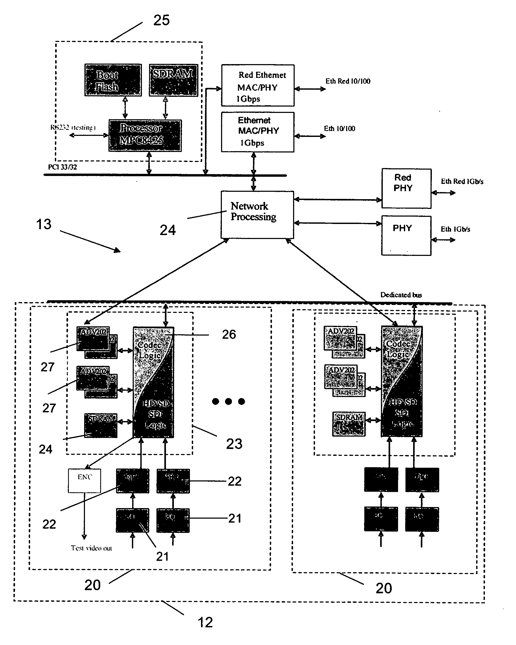
[0111] The DGU in accordance with the first embodiment of the present invention as described above is shown in FIG. 7. The block schematic shown describes the different functional parts provided in the DGU mezzanine.

[0112] The DGU unit receives a number of encoded signals—unicasted or multicasted on the network 13—through the redundant 1 Gb / s network interface in a number of input buffers 30 (RJ45 Magnetics—PHY). The buffered signals are processed in a processor 31 (Network processing—SDRAM—Flash). The received signals are then decoded in a decoder 32 (Codec logic—SDRAM—ADV202) and transferred across the baseboard-mezzanine interface of the multi-viewer driver 2, e.g. Hydra, to the baseboard of the multi-viewer driver 2, e.g. Hydra. This baseboard takes care of inserting the decoded image on the internal bus of the multi-viewer driver 2, e.g. Hydra. A controller block 33 (SDRAM+flash+processor) with an own redundant fast Etherne...


PUM


Abstract

A digital networked studio and the needed software services to allow the use of the system for monitoring the creation and distribution processes of real-time created content is described. Distribution problems are solved using an off-the-shelf network, e.g. using an IP based or similar data protocol, such as an IP network based distributed system architecture to bring the display controller functionality closer to the source and to replace proprietary busses used for transporting video, audio, RGB, graphical information and / or metadata with building blocks based on standard IP and compression technologies. A characteristic of such a network is to use unicast, multicast and / or broadcast technologies (based on network addresses) and to route data from one address to another. The network provides redundancy in case any of the digital generation units.

Description

TECHNICAL FIELD OF THE INVENTION [0001] The present inventions relate to multi-head display controllers and multi-head displays as well as methods of operating these displays, e.g. as used during pre-sports events and in-sports events phases of operation for metadata, process and broadcast monitoring purposes. The term “multi-head” refers to using more than one display unit, e.g. monitor, side-by-side to create a very large logical desktop. A multiple of display units, e.g. monitors, may display a multiple of different video and / or RGB images and related and / or embedded metadata (such as video characteristics or embedded audio), for example, as e.g. in broadcast studios, utilities control rooms or air traffic control. The present invention also relates to all applications for multi-screen large area displays or applications where parts of the same information have to be shown synchronously on multiple display units. Typical applications are broadcast, telecommunications, utilities, ...

Claims


Application Information

Patent Timeline
Patent Type & Authority Applications(United States)
IPC IPC(8): G06T1/00G06F15/16
CPCH04N9/12H04N7/181G06F3/1446G09G2340/02
Inventor NUYTTENS, GEERTDEWAELE, RONNY
Owner BARCO NV
Why Eureka
Try Eureka