Sewer pipe gas exhaust filter apparatus

a filter apparatus and sewage pipe technology, applied in the direction of valve operating means/releasing devices, functional valve types, transportation and packaging, etc., can solve the problems of inability to meet the needs of sewage treatmen

Active Publication Date: 2007-02-15
ODOR CONTROL SPECIALTIES
View PDF10 Cites 11 Cited by
  • Summary
  • Abstract
  • Description
  • Claims
  • Application Information

AI Technical Summary

Benefits of technology

[0008] The present invention combines a sewer venting valve unit with a gas filter unit and valving arrangement to control the direction of flow of gases through the gas filter unit. The sewer venting valve unit includes a housing communicating with a sewer pipe at a lower end with an outlet at an upper end spaced from the lower end. A sewage valve with a valve seat is positioned within the housing to control outflow through the outlet. A control rod is connected to the sewage valve at an upper end and has a float at a lower end. The weight of the float and control rod hold the sewage valve in a normally open position. When liquid sewage enters the housing at the lower end, the float is raised which closes the valve by way of the control rod to prevent sewage from being discharged through the valve outlet.
[0009] The outlet of the sewer venting valve unit is connected to a filter unit to filter gases outflowing from the sewer. The filter unit contains a gas filter medium such as activated carbon, charcoal, compost, or other material which will react with compounds in the gases from the sewage to thereby eliminate the discharge of offensive odors from the sewer pipe when gases are vented therefrom. The filter unit includes an outlet check valve and an inlet check valve. The check valves cooperate to cause gases from the sewer pipe to be channeled through the filter medium and to bypass air drawn into the sewer pipe past the filter to thereby extend the life of the filter medium. The sewer venting valve unit and the filter unit are typically located in an access chamber or manhole located at a hilltop location along the sewer pipe.

Problems solved by technology

Flow problems and other problems can develop as a result of accumulated pockets of gases within a sewer line.
On the other hand, there are situations in which vacuums can occur which can also cause flow problems and structural problems.
Unless air is allowed to be drawn into the sewer pipe at the hilltop, sewage flow is inhibited and vacuums can occur which can reach levels that will cause the sewer pipe to collapse.
However, the presence of a liquid within the housing raises the float, causing the valve to seat to prevent sewage from being discharged through the venting valve.

Method used


Image

  • Sewer pipe gas exhaust filter apparatus
  • Sewer pipe gas exhaust filter apparatus
  • Sewer pipe gas exhaust filter apparatus

Examples


Embodiment Construction

[0014] As required, detailed embodiments of the present invention are disclosed herein; however, it is to be understood that the disclosed embodiments are merely exemplary of the invention, which may be embodied in various forms. Therefore, specific structural and functional details disclosed herein are not to be interpreted as limiting, but merely as a basis for the claims and as a representative basis for teaching one skilled in the art to variously employ the present invention in virtually any appropriately detailed structure.

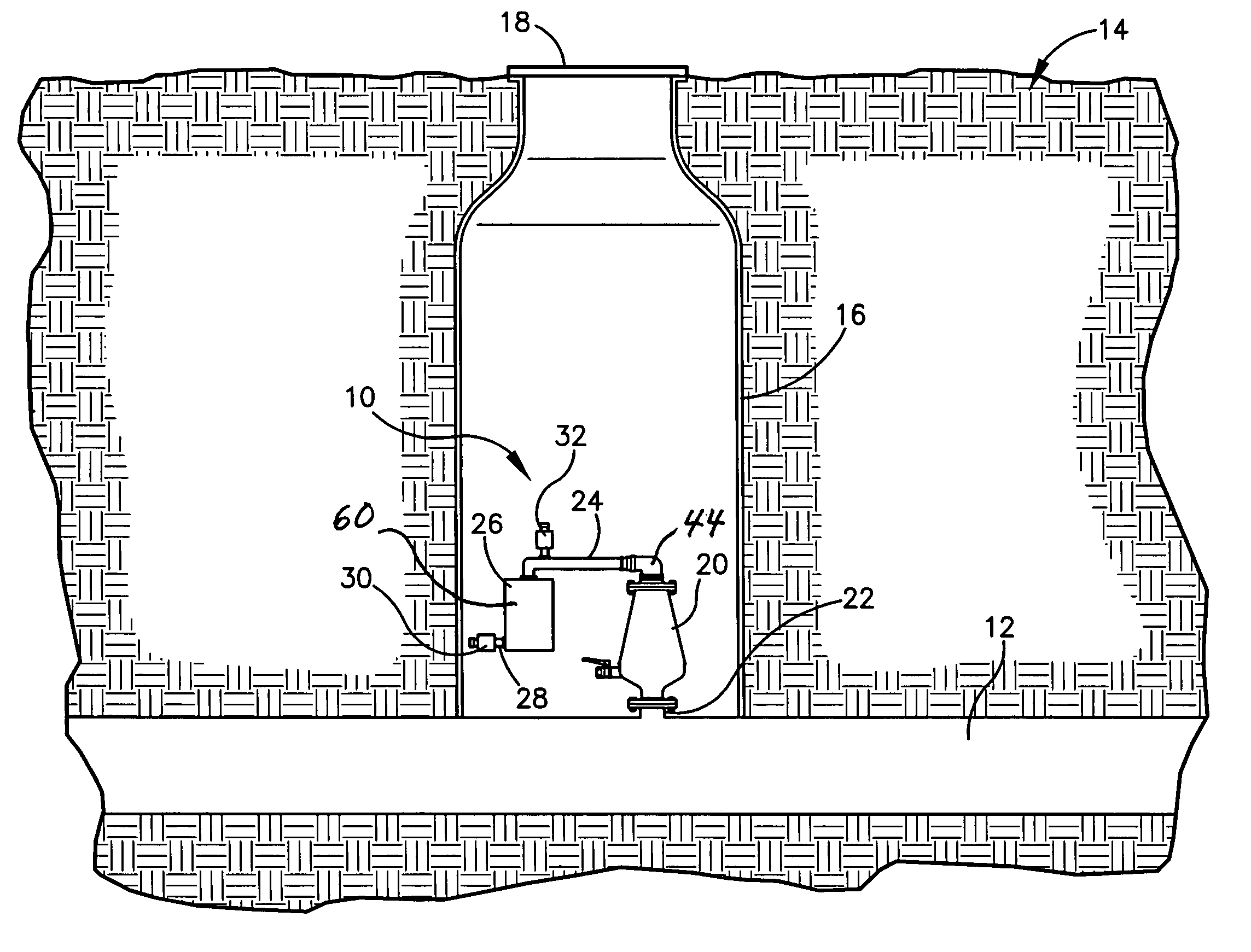
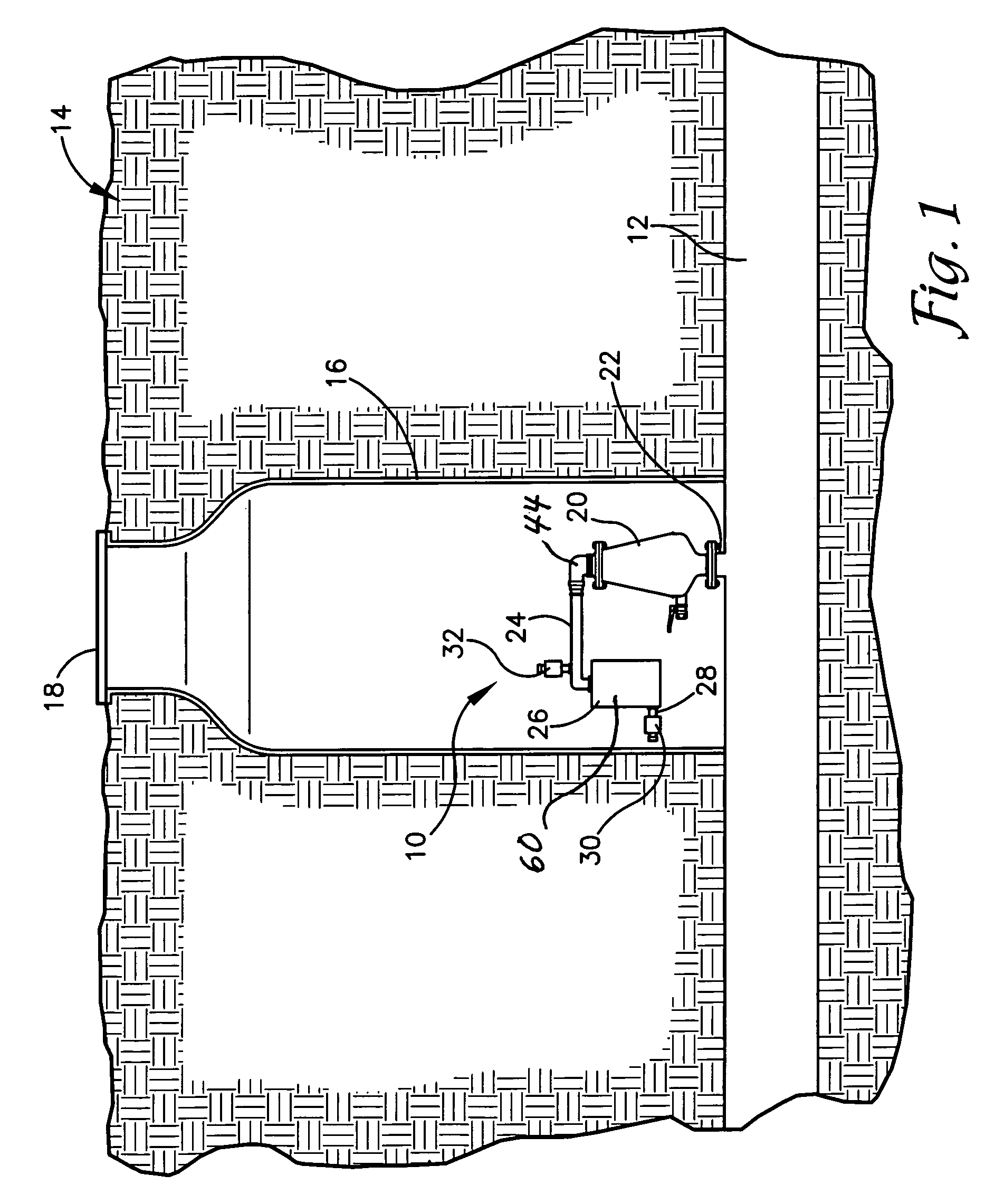
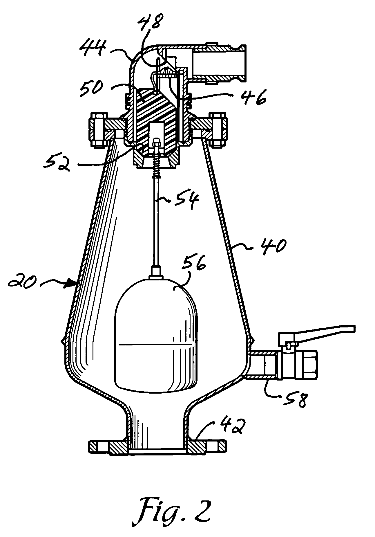
[0015] Referring to the drawings in more detail, the reference numeral 10 generally designates a sewer gas exhaust filter apparatus according to the present invention. The apparatus 10 generally includes a sewer vent valve unit 20 connected to a sewer pipe 12 (FIG. 1) and a gas exhaust filter unit 26. The vent valve unit 20 and gas filter unit 26 cooperate to allow gas from the sewer pipe 12 to flow out and filter the same, to allow air to flow into the sew...


PUM


Abstract

A sewer pipe gas exhaust filter apparatus includes a sewer vent valve unit connected to a sewer pipe and including a valve member moved into and out of engagement with a valve seat by a float member, a gas filter unit connected to the sewer vent valve unit and including a gas filter medium, and a gas flow valve arrangement to cause gases from the sewer to flow through the filter medium while bypassing air drawn into the sewer pipe past the gas filter unit. The filter medium of the gas filter unit removes chemical components from air and gas exhausted from the sewer pipe, thereby improving the odor of such exhausted gases.

Description

CROSS-REFERENCE TO RELATED APPLICATION [0001] This application claims priority under 35 U.S.C. 119(e) and 37 C.F.R. 1.78(a)(4) based upon copending U.S. Provisional Application, Ser. No. 60 / 708,203 for SEWER PIPE GAS EXHAUST ODOR ELIMINATION DEVICE, filed Aug. 15, 2005, the disclosure of which is incorporated herein.BACKGROUND OF THE INVENTION [0002] The present invention relates to sewer venting devices and, more particularly, to a sewer venting device which filters sewer gases vented to the atmosphere. [0003] Sanitary sewer pipes or sewers carry raw sewage to treatment plants where the sewage is treated. Flow problems and other problems can develop as a result of accumulated pockets of gases within a sewer line. On the other hand, there are situations in which vacuums can occur which can also cause flow problems and structural problems. For these reasons, it is sometimes necessary to vent gases from sewers to the atmosphere to prevent pockets of gases from accumulating, and at oth...

Claims


Application Information

Patent Timeline
Patent Type & Authority Applications(United States)
IPC IPC(8): E03F5/08
CPCE03F5/08Y10T137/309Y10T137/7293Y10T137/7436Y10T137/7439
Inventor MCINTIRE, MARK
Owner ODOR CONTROL SPECIALTIES
Why Eureka
Try Eureka