Luminous urn

a luminous, urn technology, applied in the field of urns, can solve the problems of inability to envisage stone structures difficult to meet the needs of people, etc., and achieve the effect of reducing cost and efficient construction

Inactive Publication Date: 2007-02-15
BLESSING RONALD LEE
View PDF16 Cites 17 Cited by
  • Summary
  • Abstract
  • Description
  • Claims
  • Application Information

AI Technical Summary

Benefits of technology

[0010] The subject of this invention is an urn made substantially of luminescent, phosphorescent, or light emitting solid surface material. The unique quality of the urn's constituting material causes its luminescent surfaces to glow while performing the function of storing crematory ashes. The preferred embodiment further permits efficient construction at reduced cost.

Problems solved by technology

These urns have the drawback of requiring numerous, delicate machining operations in which a stone slab is cored for the extraction of a column.
These bulky boxes with a complex shape also have the drawback of requiring numerous steps of fashioning and joining, and have a prohibitive cost such that a stone structure cannot be envisaged.
These modular urns are limited to cylindrical shapes.
A limitation of prior art urns includes the requirement that they be carved from a solid piece of stone, hollowed out through time consuming and expensive means.
This results in the requirement of a large source block or volume of source material.
The urns of the prior art generally also suffer from the limitation that when made from traditional materials, they cannot emit light and thus do not enhance or create the emotional effect of a luminescent urn.
Prior art urns that have attempted to overcome this deficiency fail in their attempts by requiring a separate lighting element such as a lamp, and an energy source that must be connected to a supply, battery or reservoir that must be replenished.
Without fuel there is no flame and its enhancing effect is lost.
Such a flame requires regular maintenance and poses a potential fire hazard, limiting the use of such a flame in an unattended area.

Method used


Image

  • Luminous urn
  • Luminous urn

Examples


Embodiment Construction

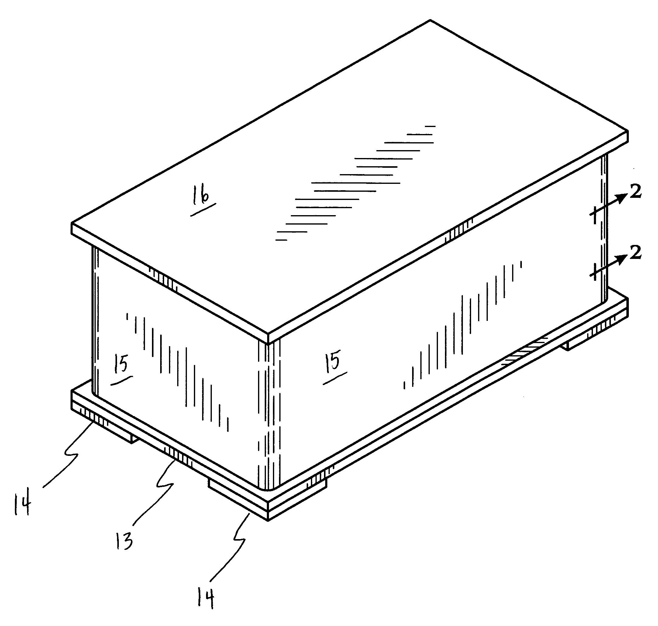
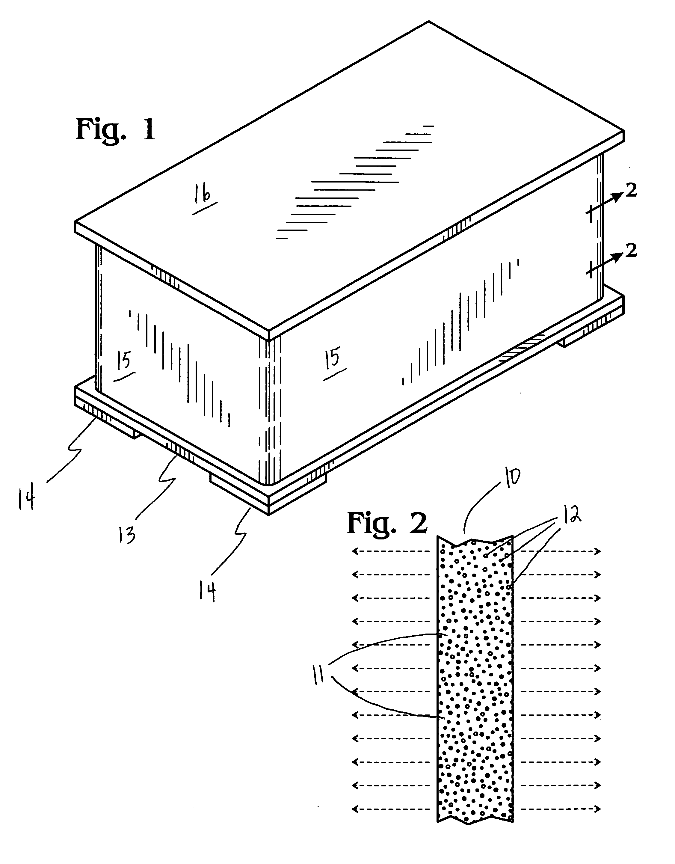
[0013] In its preferred embodiment, the urn is made from pieces of luminescent solid surface material 10 affixed together with adhesive or chemical bonding. The base 13 is a horizontal rectangular piece with four legs 14 affixed. Each leg 14 has one 90-degree angle. The 90-degree corner of each leg 14 is matched flush with the corners of the rectangular base 13. The base 13 is placed with its legs 14 facing down.

[0014] Four vertical pieces make up the vertical sides 15 of the box shaped urn. In the preferred embodiment, the width of each vertical side 15 is slightly smaller than the side of the base 13 to which it will be affixed. These vertical sides 15 are affixed to each other and to the base 13. The base 13 forms the bottom of the urn.

[0015] A rectangular piece large enough to simultaneously touch the top edge of the vertical sides 15 of the urn forms the top 16. The size of the top 16 prevents it from falling into the urn. A protrusion is affixed to the bottom surface of the ...


PUM


Abstract

A luminescent urn with a base, vertical sections, and a removable top with a structure comprised principally of luminescent solid surface material.

Description

BACKGROUND [0001] This invention relates to urns used to store cremation ashes, specifically to urns made of solid surface material incorporating a luminous, phosphorescent, or light-emitting property. Such a lighted monument is thought to broaden and enhance the impact of seeing placement of remains and contemplating the contents of the urn. [0002] Prior art discloses how to make urns of solid stone. Document FR 2 681 624 describes a stone urn made by assembling a tubular stone block with stone disks of the same diameter forming a lid and pedestal, one face of the disk being bonded to the end rim of the block. These urns are designed to be preserved and concealed within a funerary monument slab, the urns being inserted in a cylindrical bore of the slab. These urns have the drawback of requiring numerous, delicate machining operations in which a stone slab is cored for the extraction of a column. The column is then truncated to obtain disks while the axial part of the remainder of t...

Claims


Application Information

Patent Timeline
Patent Type & Authority Applications(United States)
IPC IPC(8): A61G17/00
CPCA61G17/08A61G17/007
Inventor BLESSING, RONALD LEE
Owner BLESSING RONALD LEE
Why Eureka
Try Eureka